Powerdynamo brings new ignition & light
to your vintage motorcycle
![]()
![]()
|
Powerdynamo brings new ignition & light |
|||||
|
|
|||||
| assembly instructions for system 74 01 999 00 |
Version 06.07.2012 |
|
|
Designated use This system is designated to replace stock dynamo/alternator & ignition systems in vintage and classic motorcycles whose engine characteristics have not been modified aftermarket. This system is not a tuning system and it will not bring significant increases in engine output. It does however significantly enhance roadworthiness and comfort by offering better lighting, better function of side indicators and horn and, compared with the aging stock systems, increased reliability. As our system does not tamper with engine characteristics it does not increase emission of gaseous pollutants and noise. In most cases emission of pollutants should even be reduced due to better combustion. If used as designated the system therefore will not normally infringe the existing legal status of the motorcycle (this statement is valid for Germany, for other countries, please check locally against your road licensing regulations). This system is not suitable for use in competition events. If used other than the designated way, warranty will be voided and it might well be that you do not obtain the desired results or, worst you loose legal roadworthiness. |
| Please read these
instructions fully and carefully before starting work on your motorcycle Please bear in mind that any modification of the material as well as own repair attempts which have not been agreed with Powerdynamo may result in a loss of warranty. Also, please take note of the information provided on the information page for this system. Check that what you have bought really corresponds to the motorcycle you have. Wrong ignition settings may damage your engine and even hurt you during kickstart (violent kickbacks). Be careful during the first test runs. If needed change settings to safer values (less advance). During assembly check carefully that the rotor (flywheel) does not touch the stator coils or anything else, which may happen due to various circumstances and lead to severe damage. |
|
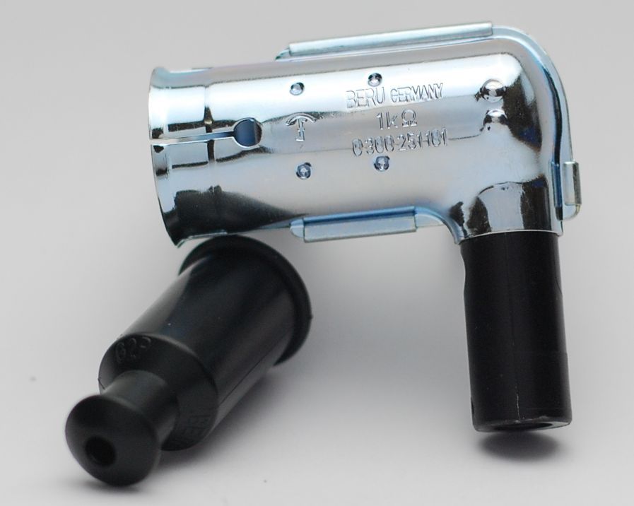
| Please always use shielded spark plug caps (but not more than 5Kohm) with this system as the hall trigger element is very sensible and may catch the emission of a spark which can lead to ignition disturbances, even failure. | |
| Our systems are NOT tested for use with third party electronic devices and may cause damage to such parts. Possibly existing electronic tachometers will not work with the new system. Read our information for suitable solutions. Possibly existing safety switches and electronic valve controls are not supported. It might be that your motorcycle was originally equipped with an ignition that did limit top speed for legal reasons. The new system does not have such a facility, so check your legal situation beforehand. | |
| If you have no expertise for the installation have it done by an expert or at a specialist's workshop. Improper installation may damage the new system and your motorcycle, possibly even lead to bodily harm. | |
| Before you order a system, please check whether a puller
tool for the new rotor is included in the kit. If not,
better order it at the same time. You might want to order light bulbs,
fuse, horn,
flasher
unit etc. Never use anything other than the recommended puller tool to pull the new rotor again. Damage to the rotor as a result of use of other tools or methods is not covered by warranty. |
|
| The rotor is sensible to blows (including during transport). Before assembly, please always check for damage (on rotor without magnet plastification try to push the magnets aside with your fingers). After impact the glued in magnets might have broken loose, sticking to the rotor solely by magnetic force, so that one does not notice right away. During engine run the damage would be considerable. Before placing the rotor onto the engine, please make sure that its magnets have not collected any metal objects such as small screws, nuts and washers. That equally would lead to severe damage. | |
|
|
If you have access to the Internet, best view those instructions online. You get larger and better pictures by clicking onto them and possibly updated information. System list at http://www.powerdynamo.biz |
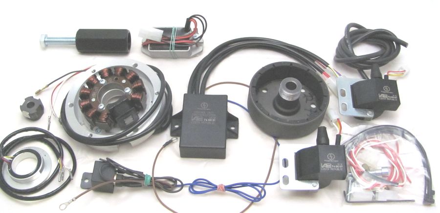 |
You should have received those parts:
|
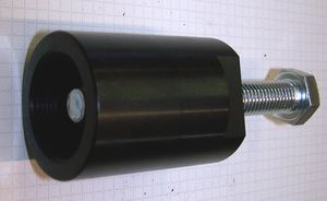 |
To pull the new rotor, use only the provided puller M27x1,25 (order-no.: 72 98 799 99). Note: Never use a claw puller, a hammer or any other device, that will shake the magnets off. |
|
|
|
| Make sure your Honda rests securely, preferably on an elevated work bench and that you have good
access to the engine. You do yourself a favour when you first completely read the instructions before you start work. Notably do not remove the stock alternator before you have installed the new hall element trigger unit on the camshaft! This will help you in timing using the stock rotor markings. Disconnect your battery and take it out
of the motorcycle for the time of work. |
|
|
|
|
Short overview of
work to be done: |
|
|
|
|
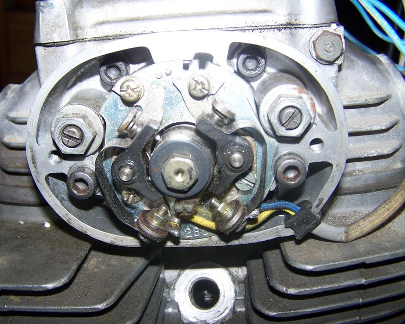 |
Remove the cover from the points box, remove the 2 holder screws and take the points plate off. Remove the cam screw and take the govenor off. |
|
|
|
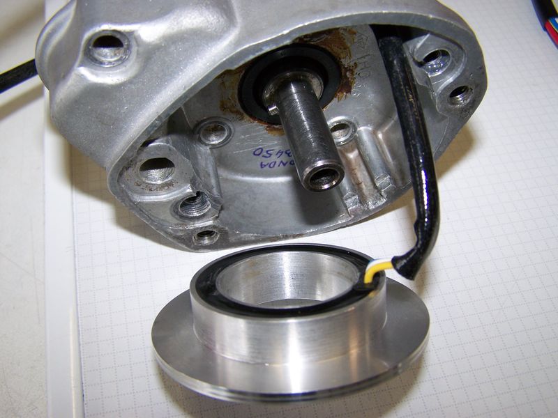 |
Lead the wire of the new hall element through the wire opening of the points box from inside out. Should there not be a grommet, use the one supplied. (picture shows box from CB450) |
|
|
|
 |
Place the hall element into the seat of the points plate and provisionally fasten it with the 2 screws just the way the points plate was fastened. Do not forget the washers! |
|
|
|
| 0 | |
 |
|
|
|
|
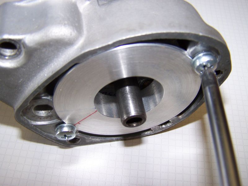
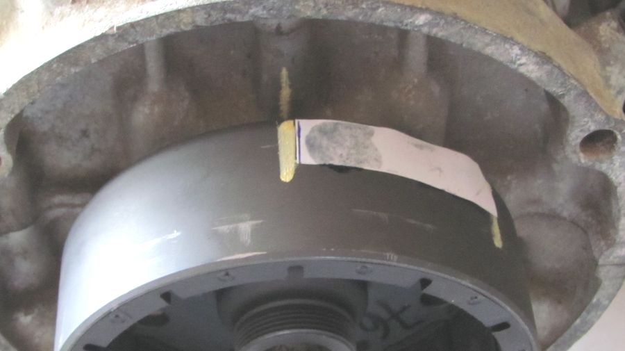
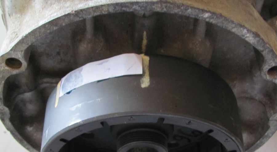
| Remove the 2 spark plugs (to take compression
off) and bring the crank into such a position that the newly made
marking (here labeled H) aligns to the timing mark on the stator coils.
This done, the left cylinder is in a position of 50� before TDC. The
left cylinder is your cylinder firing first (later called first
cylinder) It is important to keep this position until you have set up the magnetic hall rotor. |
|
 |
|
|
|
|
|
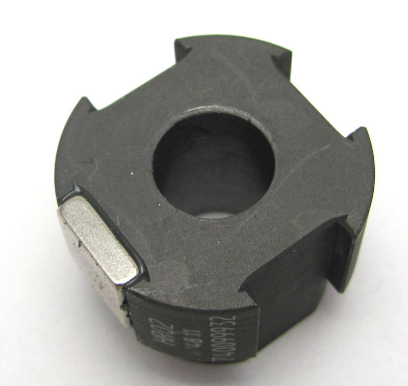
With the crank still in this 50� before TDC left cylinder, slide the
magnetic rotor over the camshaft end. The part with the 2 stud screws
facing away from engine so that you can fasten the screws later on.
You must be able to turn the magnetic rotor without modifying the
camshaft position. |
|
|
|
|
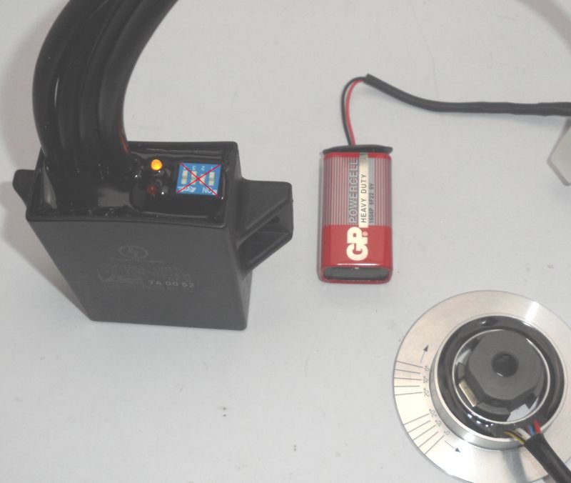
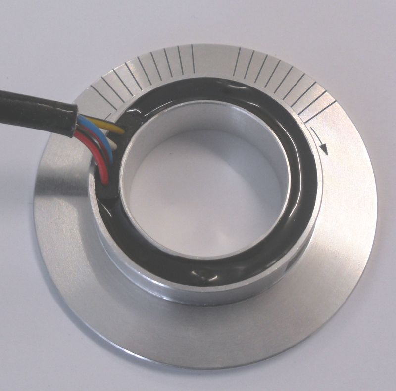
| To set this magnetic rotor into correct position you must setup some initial wiring and you need - briefly for setup only - a battery (any from 6 to 12volts) | |
|
|
|
|
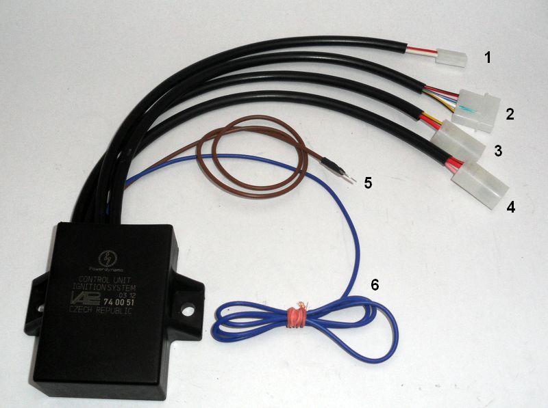
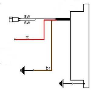
You may see the graphic illustration of the following information in wire diagram 7451-2 |
|
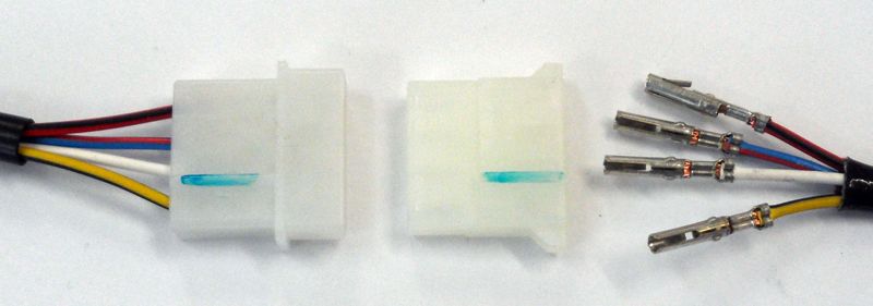
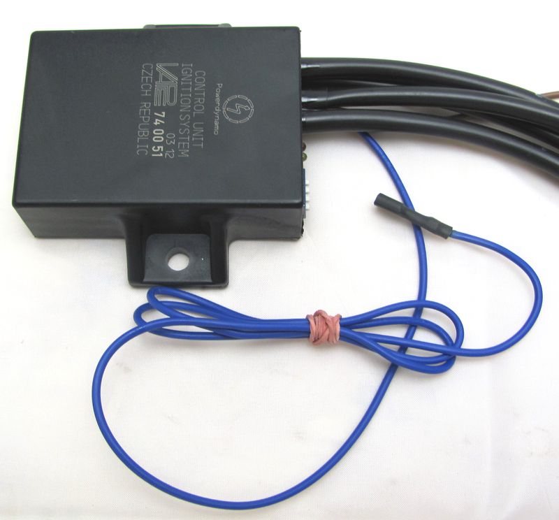
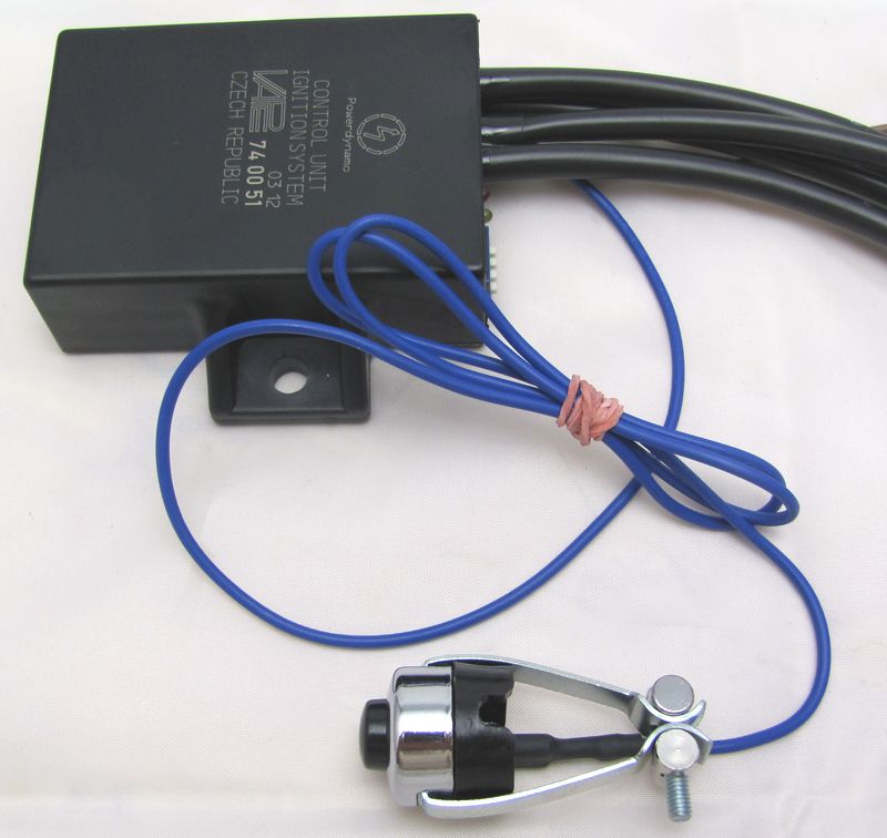
| Start with familiarising with the wires and plugs at the advance unit (a box labeled 74 00 51). | |
|
You have got there:
|
| Start with connecting the wire from the hall sensor unit to the advance. | |
|
After You have led the wire from the hall unit though possible tight openings you put the plastic plug cover on the terminals at the wire. Make sure that the wire colours match 1:1 from hall wire to advance. Both plug parts have small elevations to give you some orientation which side to connect together. In the picture we have highlightend those elevations in green. Please double check that you have all wire colours one to one (same colour to same colour). |
|
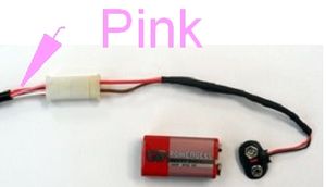
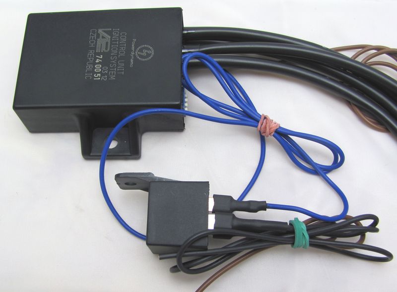
Identify the wire bundle at the advance which contains the pink wire. (Pos. 4
in above overview picture). You also got a (setup) cable with wires
red and white, the plug of which matches the plug at advance containing the pink.
Here you now connect the plugs and get
To set timing you first need to connect a battery ( 6, 9 or 12V) to the setup cable. Red to plus and white to minus, do not confuse this! |
|
Sure that the hall unit shown here as a free part is at this point already
fixed to the engine.
When you turn the still loosely on the shaft sitting hallrotor
and have the battery connected you will notice that one of the diodes
starts to shine, turning further stops to shine until some 180 degrees
further the second diode does the same. |
|
|
|
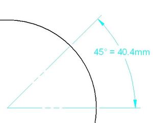
| Now you need to do some basic crank setting. For this you have to bring the crank in a position where the piston of the cylinder which fires first is 45 degrees before TDC. Those 45 degrees have nothing to do with the real advance of the system, they are some constant the system needs to find its way. | |
|
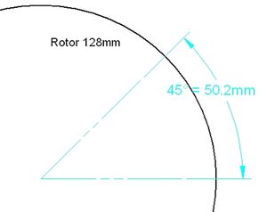
You may set the 45 degrees using the new rotor of
the Powerdynamo alternator as follows:
Now
turn the rotor anticlockwise till the second marking has reached the
position the first marking had been in - and you have set the crank into
45�! BTDC. |
|
|
|
|
|
|
|
With crankshaft in this position (45 degrees before TDC of first firing cylinder) and setup wire connected you turn the (loosely fitted) hall rotor into driving direction of the shaft - clockwise - until the yellow diode starts shining. Than slow your turning until the yellow diode stops shining. In this position (moment it stops shining) carefully fasten the hall rotor without changing its position relative to the crank. Timing is now set. The rest is done by the advance unit. |
|
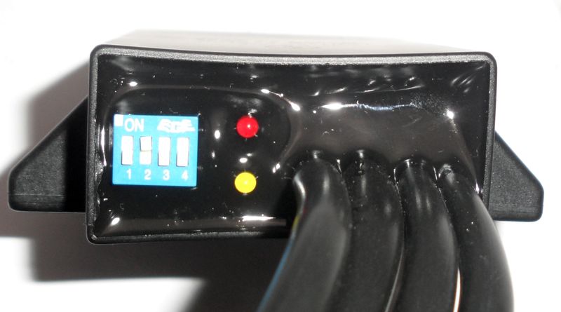
Setting the different characteristics needed by a system (advance in relation to crank revs) is done by the advance unit. IT contains different curves. The needed one is selected by setting the n4 small switches as indicated in the instructions. |
| Take the setup cable off again. Connect the 2 twin ignition coils (wires 3 and 4), the cable (nr 1) to the alternator, the brown to goud ground and the blue to the cut off device. | |
| Ignition is now timed and ignition wiring set up. | |
|
|
|
|
To stop engine run, the blue wire from the
advance unit has to be connected to ground. As long as it has ground, you can not start the engine. In case of ignition trouble always first disconnect this blue wire to exclude some error in the switch off circuit (happens quite often!). DO not disconnect the wire with engine running. It carries voltage which could hurt you. Please note that to use the relay, you need a working battery. Otherwise the relay can not operate and your engine can not be started! |
|
|
|
|
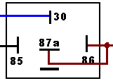
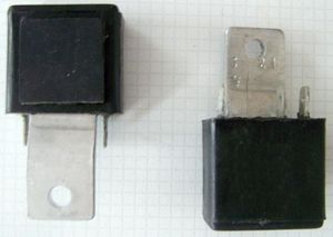
The best way to connect the blue kill wire to ground is to use the supplied switch off relay (please note that it is not any, but a special relay) The brown wire from pins 86 and 87a connect to ground. The black from pin 85 connects to a terminal at the main switch which carries voltage when switch is in ON position. Pin 30 of the relay takes the blue kill wire from the advance
|
|
|
|
|
If you want to drive without battery you have to use some other means to connect the blue wire to ground for switch off (that is to connect at least as long as it takes till engine stand still) The obvious way is to use a kill switch. Some motorcycles might already
have an emergency cut off which might do the same (check whether it
connects against ground). Note that your handlebar should have good
ground. Otherwise engine will not cut off, but you may feel the voltage as
you than are ground!
|
|
|
|
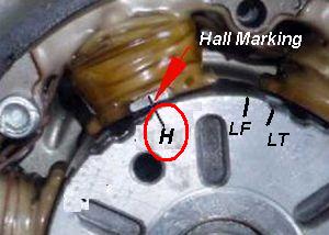
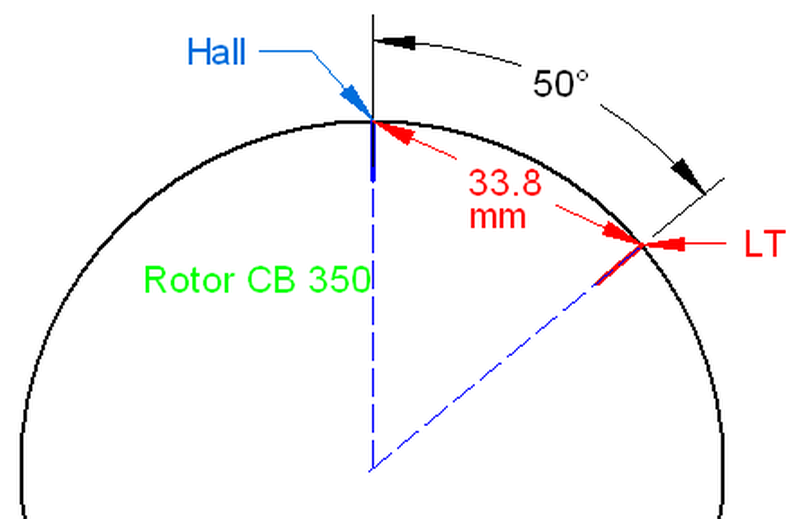
| here you see the magnetic rotor and the twin hall element (90 degrees) for the Honda 350. Honda adjusts left cylinder first. As the camshaft turn anticlockwise, you set up with red diode and connect the cable with the red/black wire to the ignition coil of the left cylinder. | |
|
|
|
|
|
|---|---|
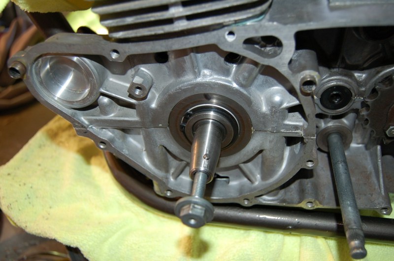 |
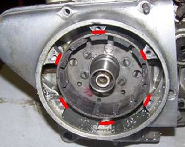
Now you can disassemble the stock rotor and stator. Remove the pin from the crankshaft, otherwise you couldn't mount the new rotor. |
|
|
|
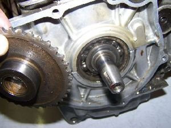 |
Remove also the pinion and the chain of the starter mechanism. Note that this (starter) facility will no longer be supported! |
|
|
|
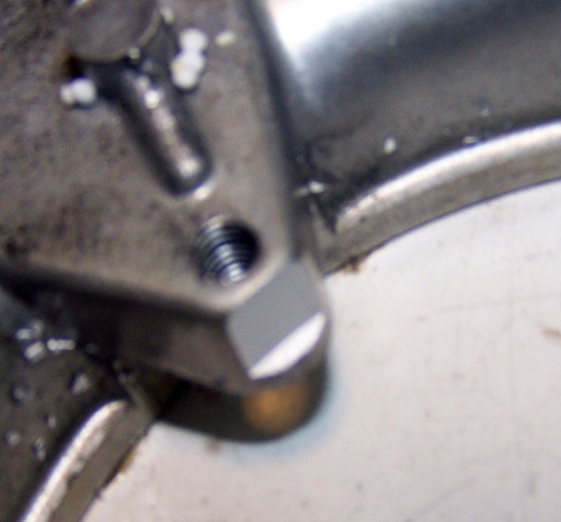
| Unfortunately you will have to physically modify the magneto cover to some extent. Problem is that the outer diameter of the rotor (113mm) interferes with the holding lugs for the stock stator. Those will need to be shortened (best on a lathe, but also with other tools such as dremel) | |
 |
|
|
|
|
| After you have opened the inner diameter of the cover wide enough for the 103mm rotor, fix the adapter plate to the cover using the 3 countersunk screws. | |
 |
|
|
|
|
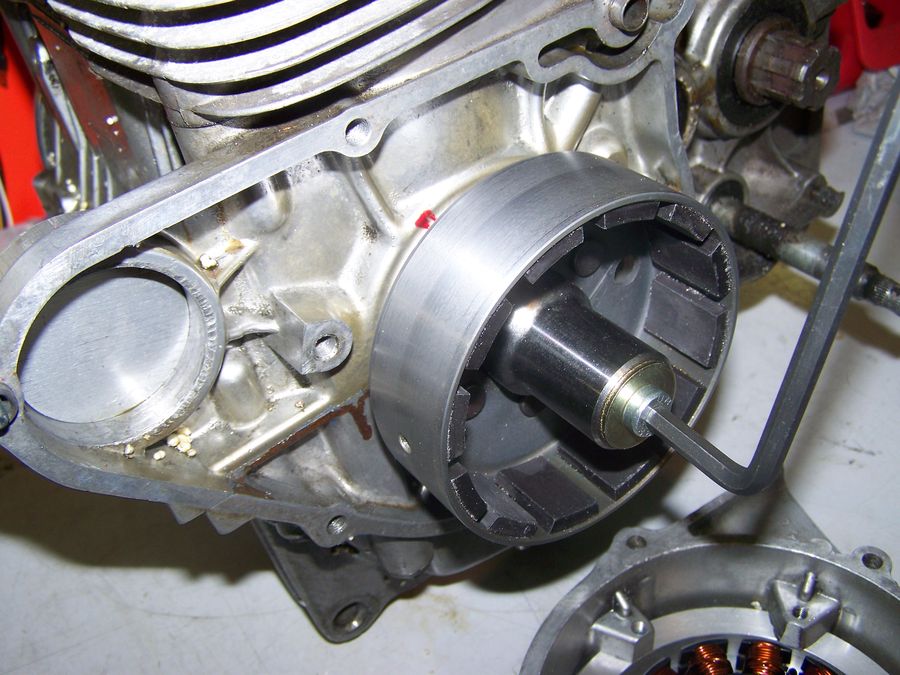 |
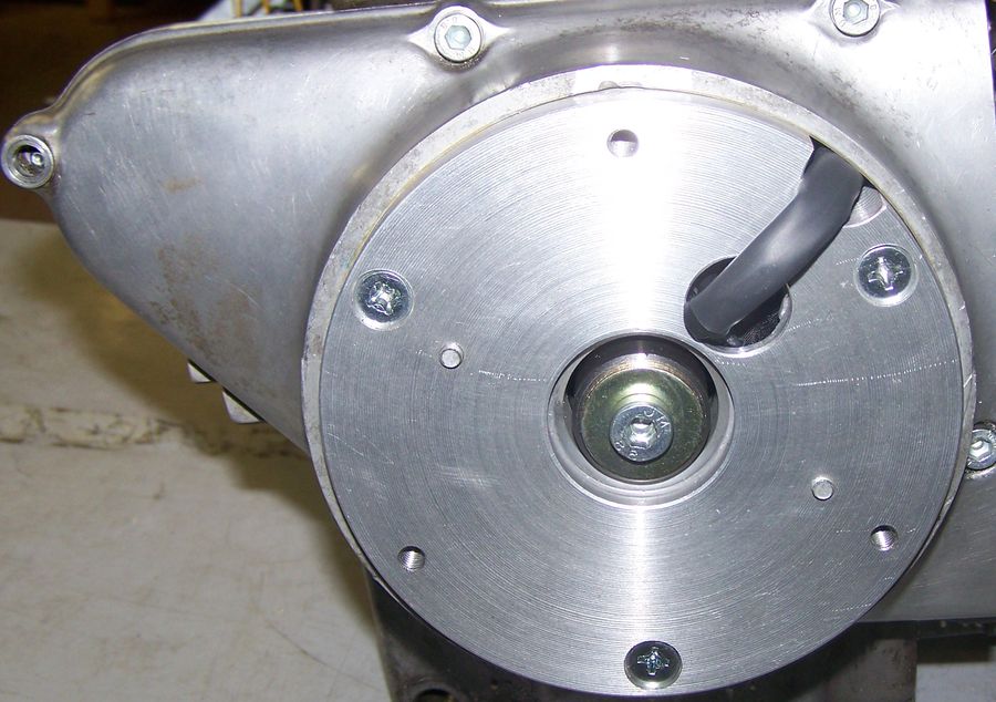
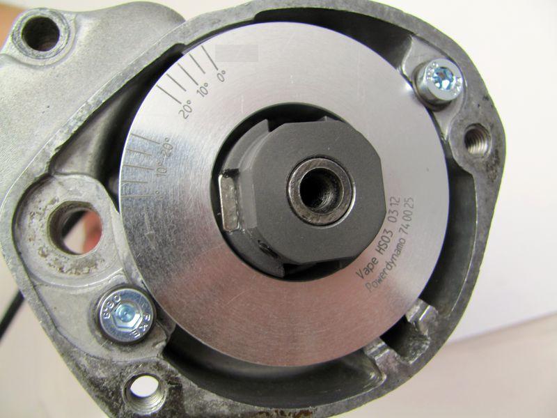
Place the new rotor (flywheel) onto the shaft. No special positioning required, but check that it runs freely. Fasten with the screw (and washer) M8.
Check that the magnets have not collected anything such as washers, screws, etc. |
|
|
|
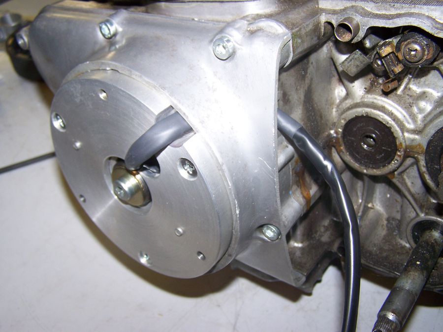 |
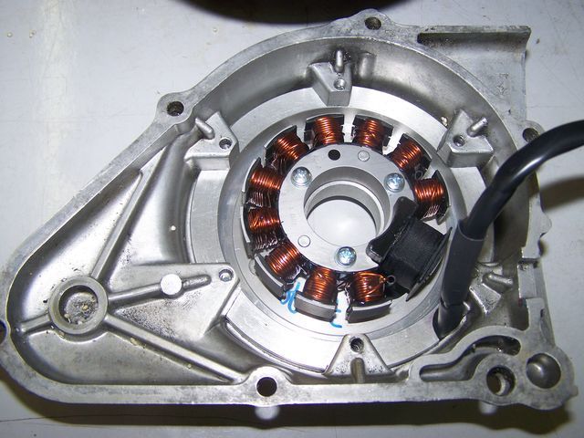
Place the magneto cover with the stator back onto the engine. Take care of the
wires, they should be placed in the engine like the wires of the stock
system and do not interfere with the rotor.
|
|
|
|
| Before installing the advance unit, have a look at the small switches at the advance unit. They activate different characteristics. There are 4 switches activating different advance curves. The following gives the possible settings for the CB175: | |
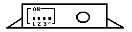 |
Curve recommended: - from start till x revs y degrees, than linear to z degrees at a revs |
|
|
|
|
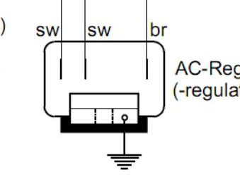
Connecting Powerdynamo alternator to lighting circuit - Versions with DC and with AC regulator |
|
|
The 2 black wires running from the stator
coil carry the voltage for lights, horn, flashers etc. They have nothing
to do with ignition. This voltage (something between 10 and 50 volts AC) has however to be stabilized (regulated) and for most uses rectified into direct current (DC) as it primarily is alternating current (AC). For this we offer different regulators: |
|
|
|
|
|
|
|
|
|
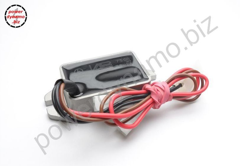
| DC Regulator: DC regulator with built in smooting condenser (73 00 799 50) | |
|
|
|
|
|
| AC Regulator: AC regulator (70 36 799 50) | |
|
|
|
|
|
|
|
|
To stop engine run, the blue wire from the
advance unit has to be connected to ground. As long as it has ground, you can not start the engine. In case of ignition trouble always first disconnect this blue wire to exclude some error in the switch off circuit (happens quite often!). DO not disconnect the wire with engine running. It carries voltage which could hurt you. Please note that to use the relay, you need a working battery. Otherwise the relay can not operate and your engine can not be started! |
|
|
|
|
|
The best way to connect the blue kill wire to ground is to use the supplied switch off relay (please note that it is not any, but a special relay) The brown wire from pins 86 and 87a connect to ground. The black from pin 85 connects to a terminal at the main switch which carries voltage when switch is in ON position. Pin 30 of the relay takes the blue kill wire from the advance
|
|
|
|
|
|
If you want to drive without battery you have to use some other means to connect the blue wire to ground for switch off (that is to connect at least as long as it takes till engine stand still) The obvious way is to use a kill switch. Some motorcycles might already
have an emergency cut off which might do the same (check whether it
connects against ground). Note that your handlebar should have good
ground. Otherwise engine will not cut off, but you may feel the voltage as
you than are ground!
|
|
|
|
|
|
Important safety and operating information |
|
# |
Safety first! Please observe the general
health and safety regulations motor vehicle repair (MVR)
as well as the safety information and obligations indicated by the
manufacturer of your motorcycle. The timing marks on the material are for general guidance only during first installation. Please check after assembly by suitable means (stroboscope) that settings are correct to prevent damage to the engine or possibly even your health. You alone are responsible for the installation and the correctness of settings. |
|
# |
Ignition systems generate high tension! With our
material right up to 40,000 Volts! This may, if handled carelessly, not
only be painful, but outrightly dangerous.
Please do keep a safe distance to the electrode of your spark plug and
open high tension cables. Should you need to test spark firing, hold the
spark plug socket securely with some well insulating material and push
it firmly to solid ground of the engine block. Never pull sparkplug caps when engine is running. Wash your vehicle only with engine at standstill and ignition off. |
|
# |
Should you have received in the kit HT cables with a fixed rubber boot(which does not contain a resistor) you might have to use spark plugs with an inbuilt resistor (or replace the cap with one containing a resistor) to comply with your local laws. |
|
# |
After installation, please check tightness of all screws, even those preinstalled. If parts get loose during run, there will be inevitably damage to the material. We pre-assemble screws only loosely. |
|
# |
Give the newly installed system a chance to work, before you start
to check and test values, or what is worse apply changes to it. Our parts have been checked before delivery to you. You will not be able to check much anyway. At any rate do refrain from measuring the electronic components (such as ignition coil, regulator and advance unit). You risk severe damage to the inner electronics there. You will not get any tangible results from the operation anyway. Bear in mind that also your carburetor, your spark plugs and spark plug sockets (even if completely new) might be the reason for malfunction. The general experience with our systems is that the carburetor will have to be re-adjusted to lower settings. Should the system not start after assembly, first disconnect the blue (or blue/white) cut-off wire directly at the ignition coil (or in some cases advance unit) to eliminate any malfunction in the cut-off circuitry. Check ground connections carefully, make sure there is a good electrical connection between frame and engine block. In case of troubles, please consult our Knowledge Base first before you send off the material to us for checking |
|
# |
The spark of classic, points based ignition systems has with about 10,000 Volts comparatively little energy and looks therefore yellow and fat (which however makes it highly visible). The spark from our system is a high energy spark with up to 40,000 Volts and therefore is needle thin focused in form, and blue in colour, which makes it not so visible. Furthermore you get spark only at kick-start operated speeds and not by pushing the kick-lever down slowly with your hand (as you might get with battery based ignitions). |
|
# |
Systems using a twin outlet ignition coils have a few peculiarities. Please observe that during tests on one side, the other has either to be connected to an fitted spark plug or securely earthed/grounded. Otherwise there will be no spark on either side. Also with such open exits long and dangerous sparks may fly all over the coil. |
|
# |
Never do electric arc welding on the bike without completely disconnecting all parts containing semiconductors (ignition coil, regulator, advance) stator and rotor need not be taken off. The same is true for soldering. Before touching electronics disconnect the soldering iron from mains! Never use copper putty on spark plugs. |
|
# |
Electronics are very sensitive to wrong polarity. After work on the system, do check correct polarity of the battery and the regulator. Wrong polarity creates short circuits and will destroy the regulator, the ignition coil and the advance unit. As a rule, wiring will always be colour to colour. Instances, where colour jumps between wires are expressly mentioned in our instructions. |
|
# |
When you handle the new rotor, take care not to damage its magnets. Refrain from direct blows to the circumference of the rotor. When transporting never put the rotor over the stator. Observe our information relative to transport of the material. |
|
# |
Do not use spark plug sockets with a resistance of more than 5kOhm. Better use 1 or 2kOhm ones. Bear in mind that spark plug sockets do age and thereby increase their internal resistance. Should an engine start up only when cold, a defective spark plug socket and/or spark plug is very probably the cause. In case of problems check high tension cables too. Never use carbon fibre HT-cables, never use so called "hot wires" which promise to increase spark. |
|
# |
It is a good idea to cover the rotor in a thin layer of oil to reduce the risk of corrosion. |
|
# |
Never use a claw puller or a hammer to disengage the rotor. Its magnets might become loose in the event. We offer a special puller for disengaging the new rotor again (see assembly instruction)! |
|
# |
Should the motorcycle not be in use for some longer period, please disconnect the battery (so existing) to prevent current bleeding through the diodes of the regulator. Though, even a disconnected battery will empty itself after a while. |
|
# |
Please do observe these remarks, but at the same
time, don't be afraid of the installation process. Remember, that before you, thousands of
other customers have successfully installed the system. Enjoy driving your bike with its new electric heart! |
|
|