Powerdynamo brings new ignition & light
to your vintage motorcycle
![]()
![]()
![]()
![]()
|
Powerdynamo brings new ignition & light |
|||||
|
|
|||||
| Assembly instructions System 70 91 999 00 |
Version 02.03.2011 |
|
If you can install and time a stock ignition and
possess basic mechanical skills, you can install a Powerdynamo! |
|
| Powerdynamo can not monitor the compliance to those instructions, nor the conditions and methods of installation, operation, usage and maintenance of the system. Improper installation may result in damage to property and possibly even bodily injury. Therefore we assume no responsibility for loss, damage or cost which result from, or are in any way related to, incorrect installation, improper operation, or incorrect use and maintenance. We reserve the right to make changes to the product, technical data or assembly and operating instructions without prior notice. | |
|
|
Please read these
instructions fully and carefully before starting work on your motorcycle Please bear in mind that any modification of the material as well as own repair attempts which have not been agreed with Powerdynamo may result in a loss of warranty. Do not cut off wires. This leads to a loss of reverse polarity protection and often results in damage to electronics. Also, please take note of the information provided on the information page for this system. Check that what you have bought really corresponds to the motorcycle you have. Wrong ignition settings may damage your engine and even hurt you during kickstart (violent kickbacks). Be careful during the first test runs. If needed change settings to safer values (less advance). During assembly check carefully that the rotor (flywheel) does not touch the stator coils or anything else, which may happen due to various circumstances and lead to severe damage. |
| Designated use This system is designated to replace stock dynamo/alternator & ignition systems in vintage and classic motorcycles whose engine characteristics have not been modified aftermarket. This system is not a tuning system and it will not bring significant increases in engine output. It does however significantly enhance roadworthiness and comfort by offering better lighting, better function of side indicators and horn and, compared with the aging stock systems, increased reliability. As our system does not tamper with engine characteristics it does not increase emission of gaseous pollutants and noise. In most cases emission of pollutants should even be reduced due to better combustion. If used as designated the system therefore will not normally infringe the existing legal status of the motorcycle (this statement is valid for Germany, for other countries, please check locally against your road licensing regulations). This system is not suitable for use in competition events. If used other than the designated way, warranty will be voided and it might well be that you do not obtain the desired results or, worst you loose legal roadworthiness. The charging system is only suitable for use with rechargable 12V (6V systems 6V) lead-acid batteries with liquide electrolyte or sealed lead-acid batteries, AGM, Gel. It is not suitable for use with nickel-cadmium, nickel-metal-hydride, lithium-ion or any other types of recharchable or non rechargable batteries. This is a replacement system and not a copy of the stock material. The parts in this system therefore look different and might fit differently (notably ignition coil and regulator) requiring some adaptation by you. |
|
| During assembly imperatively start with assy of engine based parts to see that those really fit before you start fitting the external parts. In many cases customers assemble those first and thereby often modify them in breach of warranty which renders them unfit for renewed sale. Replacing old ignition systems is not a matter of taking something from a supermarket shelf as there have been very many types, versions and possibly unknown aftermarket modifications which harbour plenty of room for error. | |
| Our systems are NOT tested for use with third party electronic devices (such as GPS, mobile phones, LED lighting etc)and may cause damage to such parts. Possibly existing electronic tachometers will not work with the new system. Read our information for suitable solutions. Possibly existing safety switches and electronic valve controls are not supported. It might be that your motorcycle was originally equipped with an ignition that did limit top speed for legal reasons. The new system does not have such a facility, so check your legal situation beforehand. | |
| If you have no expertise for the installation have it done by an expert or at a specialist's workshop. Improper installation may damage the new system and your motorcycle, possibly even lead to bodily harm. | |
| Before you order a system, please check whether a puller
tool for the new rotor is included in the kit. If not,
better order it at the same time. You might want to order light bulbs,
fuse, horn,
flasher
unit etc. Never use anything other than the recommended puller tool to pull the new rotor again. Damage to the rotor as a result of use of other tools or methods is not covered by warranty. |
|
| The rotor is sensible to blows (including during transport). Before assembly, please always check for damage (on rotor without magnet plastification try to push the magnets aside with your fingers). After impact the glued in magnets might have broken loose, sticking to the rotor solely by magnetic force, so that one does not notice right away. During engine run the damage would be considerable. Before placing the rotor onto the engine, please make sure that its magnets have not collected any metal objects such as small screws, nuts and washers. That equally would lead to severe damage. | |
|
|
If you have access to the Internet, best view those instructions online. You get larger and better pictures by clicking onto them and possibly updated information. System list at http://www.powerdynamo.biz |
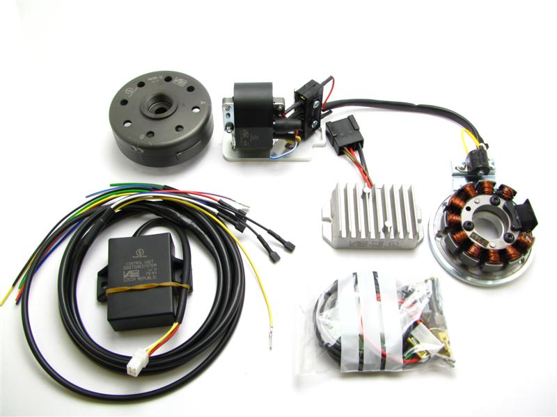 |
You should have received those parts:
* If you want (or need) to renew at your bike the entire wiring, please check:
|
|
Please pay attention: The sensor is not screwed tight on the ground plate, it has to be adjusted by yourself. The stator is not screwed tight on the ground plate. When you mount the ground plate on the crank case, you have to remove the stator. |
|
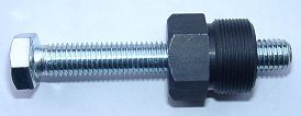 |
To disengage your new rotor again, you will need a
puller M27x1.25 (part-no.: 99 99 799 00 -Not provided!-).
Note: Never use a claw puller, a hammer or any other device, that will shake the magnets off. |
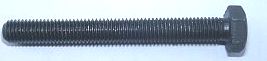 |
To pull the old rotor, you will need a puller tool M10x90 (part-no.: 89 99 026 00 -Not provided!-). |
|
|
|
| Make sure your AWO
rests securely on her stand, preferably on an elevated work
bench and that you have good access to the generator side of the engine.
Disconnect your battery and take it out of the motorcycle. Note that should you be installing a 12 volt system, you will either need a 12 volt battery or you use the option of driving without. You will still have to replace all lightbulbs to 12 volt ones however in that case too. The horn may stay at 6 volts. For driving without battery, please observe our information on driving without battery. Technical it is possible to drive your bike without the battery. But consult your local road traffic regulators. |
|
|
|
|
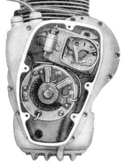 |
At first replace the old parts:
Loose the 5 hex screws of the generator cover and take it off. Disconnect the cables from your old generator and remove it. Pull off the old rotor with the puller tool (pay attention: the holding screw has a couter-clockwise tap, so you have to screw clockwise for pull off). |
|
|
|
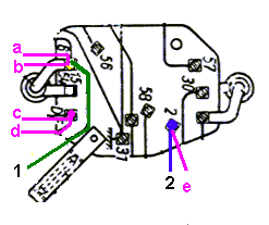 |
Look in the open lamp casing for the harness (3 wires are coming from the motor
to the ignition lock). It is shown in the picture as
a, c and e. Replace that harness complete.
Now you have to connect the provided short green (mark 1) and blue/red (mark 2) cable pieces (that's only markers). The pictured cables b and d were gone to the old regulator. You will need them no more. You can disconnect and insulate them. |
|
|
|
| Should have your
AWO a regulator in the battery case, remove it. Remove too the cable from
the centre pin of the regulator (F) to the fuse case and cut-off both
other cables (51/61) so short as possible. These are dead wires. If you
be able and willing to pull those cables out of the harness to the motor,
do it.
ATTENTION: Do not remove any other cables from the AWO, especially not this from the battery positive pole to the ignition lock. You will need it further on. |
|
|
|
|
|
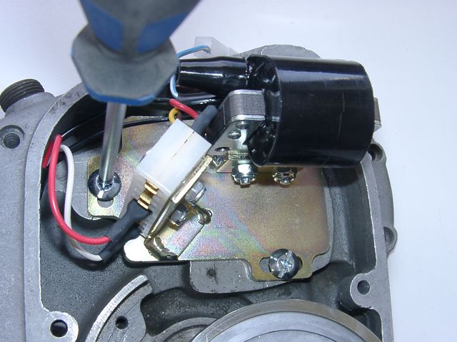
At next you have to lead the new harness (with the side with the pre-assembled plugs) through the motor case from the outside to the inside of the motor (push the plugs one after another through). Screw the ignition cable in the new ignition coil, pull over the grommet and lead the cable in the motor too. The ignition coil unit hang loose on the cables, it's not screwed down. |
|
|
|
|
|
Then you have to installate the plugs on the harness. It is now easier -
the unit is not screwed down.
Take a little time for that, rather check it 3 times,
|
|
|
|
Put a plug on the yellow cable with the pin. Then connect it with the counterpart from the sensor (a yellow cable too). Now you have to put a plug on the pin of the blue/red cable. Plug it together with the blue/white cable from the ignition coil. It is the kill switch cable. Pay attention, don't damage the hanging loose parts: the both unit plates with its assembled parts and the cables with its plugs. |
|
|
|
|
|
Then you have to mount the ignition coil unit. Lay on the paper seal and put on the cover plate with the ignition coil. Screw it on with the 2 screws M6x20. Screw it not tight, so you can shift the plate (if required). The third (upper) screw hole remains idle. |
|
|
|
| Please note: Leave the pre-assembled plug connection of the ignition plate as they are. There is no matter to plug-off them. You risk a mal-connection, loose plugs or even tear-off cables. If you really need to pull out a plug, use a flat-pliers and handle the plug - not the cable!! | |
|
|
|
|
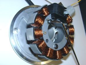
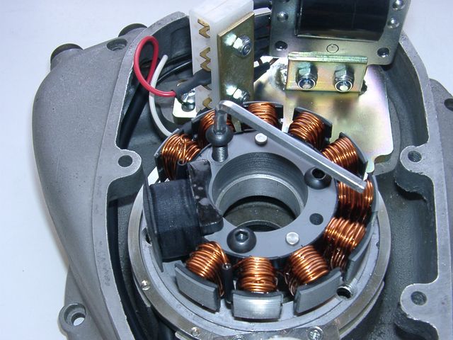
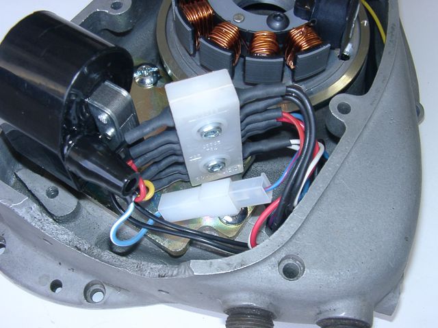
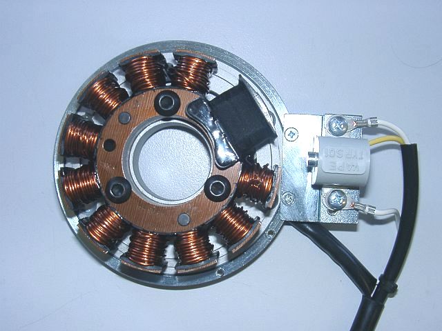
The new stator unit
is pre-assembled, so that its construction is easier to recognise. For the
mounting it has to be partly disassembled.
Pay attention: Do not damage the paint insulation of the coils. Loose the 3 hex screws, they hold the stator on the ground plate. Pull the stator in that way from the plate, so you can handle the 2 mounting holes below. |
|
|
|
|
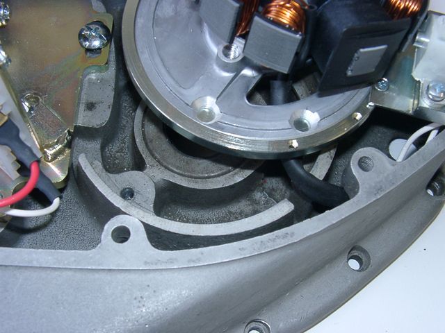
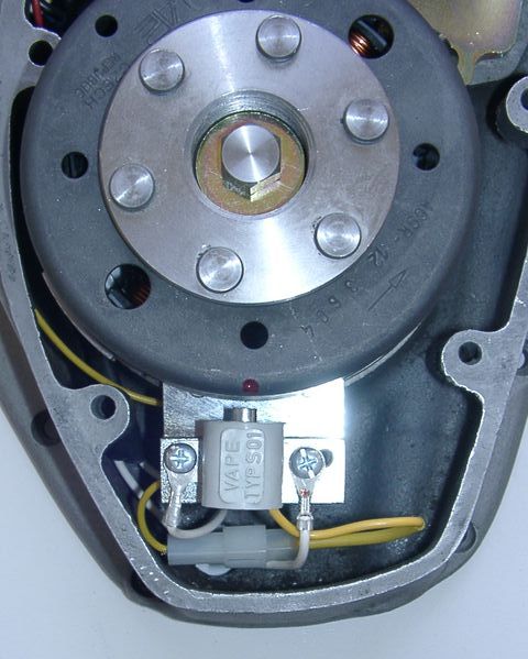
Put the pre-assembled stator plate (steel ring, aluminium plate and sensor) instead of the generator in the crank case. The sensor shows to the ground and the cable shows left upwards to the terminal of the ignition coil plate (if you look from the front on the unit). |
|
|
|
|
Screw down the ground plate (steel ring and inner aluminium plate) on the crank case with the 2 countersunk screws M6x30. The ignition coil unit hang loose on the cables further on. |
|
|
|
|
Now you have to replace the stator on the ground plate. Take care, that no cable is pinched. The coil has to be fitting good on the ground plate - nearly "hearable engage". If is it ain't so, and the coil fits "soft" on the ground plate, is a cable in the way and there is a risk of damaging by contact of the rotor. Screw down the stator with the 3 srews M6. |
|
|
|
|
|
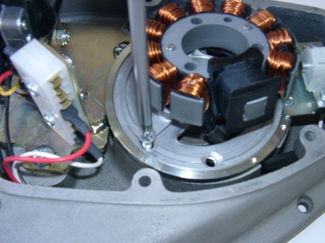
Now pull carefully the ht-cable and the harness (6 cables) afar out of the
case, as they don't trouble the rotor.
Now you can adjust the ignition coil unit with the oblong holes (if required) and tighten the both screws. Do not forget it! |
|
|
|
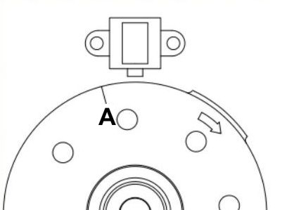 |
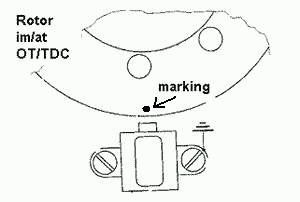
Have a look at the new rotor. You will find on its circumference a protrusion.
This one is the ignition impulse trigger. Our system reads the time the
protrusion needs to pass the sensor and calculates from that how many revs the
crank is doing to set the advance correspondingly.
That's why ignition always happens after the complete protrusion has passed the sensor. In the picture you see the position of the rotor against the sensor at max advance. At our new AWO systems, the rotor has two timing marks. For the ignition adjustment of your AWO use the timing mark that is marked with an "A". |
|
|
|
 |
Remove the spark plugs. Place the rotor loosely onto the crank and check that it may move freely
above the statorbase.
Put the new rotor handtight on the crank shaft for turning the shaft. Bring the piston into TDC. At first with the kickstarter (turning by hand) an then, for the fine adjustment, with the new rotor. You have to see the TDC marker (not the marker for the ignition point) concentric in the spy hole. |
| Take the rotor carefully off again without changing the crank's position. Reset it onto the crank in such a way that the ignition mark "A" (resp. the little red marker made by us) aligns with the left edge of the sensor bottom. In that position fasten the rotor carefully (Don't forget to use the washer!) with the left-threaded screw M7x35 provided. | |
|
|
|
|
|
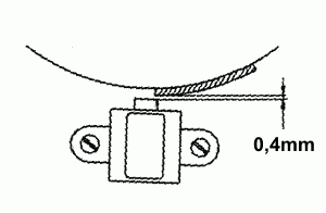
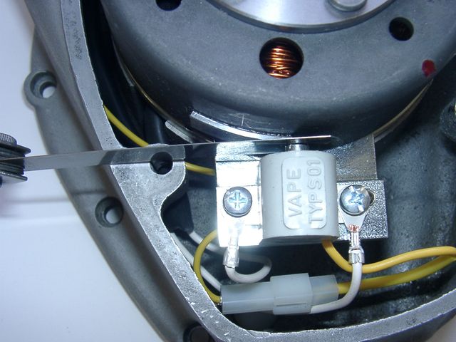
At this time you have to adjust
the gap of 0.4mm between sensor and protrusion. Turn the rotor until
the nose aligns to the sensor. Loose the holding screws of the sensor and
adjust the gap by shifting the sensor.
Don't forget to tighten the screws (also as the gap is O.K. right from the start), we don't tighten fast the screws during the preassembly! |
|
|
|
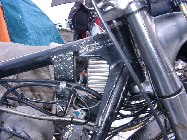
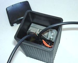
| Now you have to installate the extern parts (rectifier/regulator and the controller). You can place it beneath the tank in the frame triangle or at the sport-version in the side case. For the AWO-Tour, in case of lack of space, we have make the cables any longer. So you can hide the parts in an empty battery case (see our offer). If you like to use this option, you have to saw off one of the both stays. This is not a breach of warranty, as far as you don't saw into the case and you really only cut off the stay. | |
|
|
|
|
|
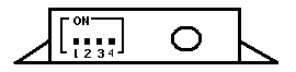 |
Take a look to the little blue dip-switch block at the upper flat side of the black ignition advance unit. There are 4 little switches, they are pre-positioned by us. They select the correct ignition advance curve. Please don't change the switch position and check it after the work. All switches has to be OFF (must shown to the digit). Otherwise your system will not or not really function. |
|
|
|
| Now you have to lay the harness on the frame: At first lead the harness upwards the frame beneath the tank. Here splits the new harness. The cable with the 2 wires goes to the lamp, that with the 7 wires goes along the frame backwards (maybe to the earlier position of the battery). Fix the cables with cable fixers. | |
|
|
|
|
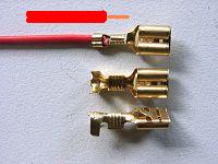
If you have layed the cables and, if necessary, shortened, you have to mount the wire-end-terminals on the cable ends. Please use the included 6.3mm receptacles. Be carefully: the insulation has to be clamped on the rear end (strain relief) and the skinned wire on the front end of the plug. (See picture) After that they will be inserted in plastic plugs. |
|
|
|
|
|
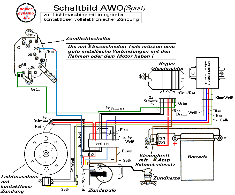
Ignition lock cables:
In the lamp casing you have to change the cable markers (hopefully you have they installed) against the cables of the same colour.
|
|
|
|
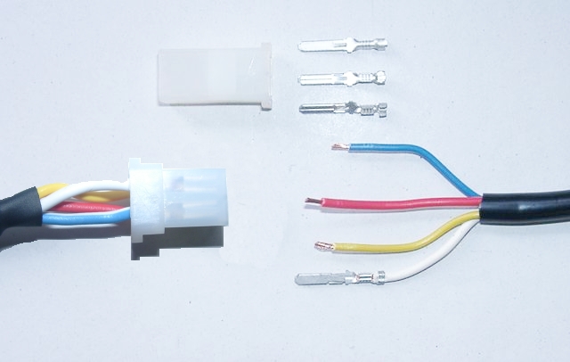 |
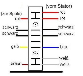
Plug to the advance unit: This relates to the cables red, yellow, blue and white from the generator's wiring. At first you have to cut the cables to the required length (tours or sports) and then to clamp the
terminals.
Following insert the 4 wires (blue, red, yellow and white). Make sure that the terminals engage securely in the housing and that you connect:
|
|
|
|
|
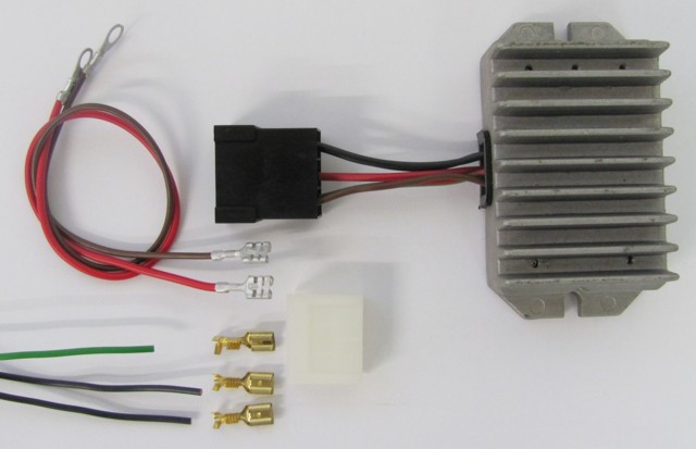
Plug to the regulator/rectifier: First attach the supplied terminals on the green (charge control, only when driving with battery) and the two black
wires.
Then insert the green and the two black wires into the included compact plug. Furthermore the two provided DC output cables (red & brown) will be attached to this plug. (see below!) |
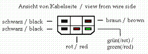 Seen from the rear (cable) side |
Please ensure that here is color on color - as described below. There should be about the connector no color change (except: green of the wiring to green/red of the
regulator/rectifier)!
Attention: Any confusion between plus and minus (with the DC versions) leads to immediate destruction of the regulator. This will not constitute a warranty case as it is negligence! One can recognize a burnt regulator mostly by its sharp smell. |
|
|
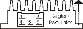
The new regulator/rectifier has a compact plug with 6 positions, of which one is not used. A female plug cover fitting to this plug is delivered. Into this female plug you have to insert the following wires (which have terminals that snap into the plug): |
| The two black cables leading from the generator ... |
... connect to pins 1/4 of the new regulator (from there equally black wires lead inside the unit). It does not matter which wire connects to which of the both terminals (1/4) as they carry alternating current. |
| The new brown cable with the round eye terminal ... |
... connects pin 3 of the regulator unit (from there equally a brown wire goes inside the unit) with the negative pole of the battery or (in case you drive without battery) to ground (chassis). |
|
The new red cable with the round eye terminal ... Take care: |
... connects to pin 5 of the new regulator (from there equally a red wire goes inside the unit). Here your regulated positive voltage comes out to connect to battery plus, or (in case you drive without battery) to the voltage input terminal of the main switch (ignition lock, German bikes: pin 51/30). |
| Make sure that you have a 16A-fuse between battery and vehicle circuitry. | |
|
The green/red wire at pin 6 of the new regulator ... Remark: |
... is for the charge control light. You connect there the wire that formerly did run from the control light to the original regulator. Sure that this control only functions with a battery present. Should you drive without battery but still connect the wire, you will see that the light glows even as the generator generates voltage. So without battery, do not connect it. |
| Please check once again that there is no color change over the connectors (plugs) (except as
described).
If you want to drive without battery, then the brown wire is connected to ground, best to the place where the former minus of the battery were connected. The red wire is connected to the cable that previously went from the battery to the ignition switch. If you want to drive with battery, connect the brown wire to "minus" of the battery and the red wire to "plus" additional to the stock cables. Do not disconnect these stock cables - it's the connection to the electrical consumers of your motorcycle. Finally - and before installing the battery and before the first kickstart - please re-check carefully all connections and fitments against the wiring diagram (see here). Do check battery and light bulbs for correct voltage (12V). Should something not work, please consult our trouble-shooting guide on our homepage. As a first step disconnect the blue wire from the coil and re-test. |
|
|
|
|
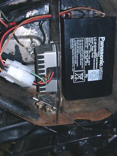
| At next will be the rectifier/regulator (it is pre-assembled on a mounting plate) installed under the rear tank mounting. For that unscrew the nut on the transverse stay (spanner 13). Put on the new mounting plate with the rectifier/regulator (the cooling ribs shown to the top) and fasten it with the nut and a washer. | |
|
|
|
|
|
Important safety and operating information |
|
# |
Safety first! Please observe the general
health and safety regulations motor vehicle repair (MVR)
as well as the safety information and obligations indicated by the
manufacturer of your motorcycle. The timing marks on the material are for general guidance only during first installation. Please check after assembly by suitable means (stroboscope) that settings are correct to prevent damage to the engine or possibly even your health. You alone are responsible for the installation and the correctness of settings. |
|
# |
Ignition systems generate high tension! With our
material right up to 40,000 Volts! This may, if handled carelessly, not
only be painful, but outrightly dangerous.
Please do keep a safe distance to the electrode of your spark plug and
open high tension cables. Should you need to test spark firing, hold the
spark plug socket securely with some well insulating material and push
it firmly to solid ground of the engine block. Never pull sparkplug caps when engine is running. Wash your vehicle only with engine at standstill and ignition off. |
|
# |
Should you have received in the kit HT cables with a fixed rubber boot(which does not contain a resistor) you might have to use spark plugs with an inbuilt resistor (or replace the cap with one containing a resistor) to comply with your local laws. |
|
# |
After installation, please check tightness of all screws, even those preinstalled. If parts get loose during run, there will be inevitably damage to the material. We pre-assemble screws only loosely. |
|
# |
Give the newly installed system a chance to work, before you start
to check and test values, or what is worse apply changes to it. Our parts have been checked before delivery to you. You will not be able to check much anyway. At any rate do refrain from measuring the electronic components (such as ignition coil, regulator and advance unit). You risk severe damage to the inner electronics there. You will not get any tangible results from the operation anyway. Bear in mind that also your carburetor, your spark plugs and spark plug sockets (even if completely new) might be the reason for malfunction. The general experience with our systems is that the carburetor will have to be re-adjusted to lower settings. Should the system not start after assembly, first disconnect the blue (or blue/white) cut-off wire directly at the ignition coil (or in some cases advance unit) to eliminate any malfunction in the cut-off circuitry. Check ground connections carefully, make sure there is a good electrical connection between frame and engine block. In case of troubles, please consult our Knowledge Base first before you send off the material to us for checking |
|
# |
The spark of classic, points based ignition systems has with about 10,000 Volts comparatively little energy and looks therefore yellow and fat (which however makes it highly visible). The spark from our system is a high energy spark with up to 40,000 Volts and therefore is needle thin focused in form, and blue in colour, which makes it not so visible. Furthermore you get spark only at kick-start operated speeds and not by pushing the kick-lever down slowly with your hand (as you might get with battery based ignitions). |
|
# |
Systems using a twin outlet ignition coils have a few peculiarities. Please observe that during tests on one side, the other has either to be connected to an fitted spark plug or securely earthed/grounded. Otherwise there will be no spark on either side. Also with such open exits long and dangerous sparks may fly all over the coil. |
|
# |
Never do electric arc welding on the bike without completely disconnecting all parts containing semiconductors (ignition coil, regulator, advance) stator and rotor need not be taken off. The same is true for soldering. Before touching electronics disconnect the soldering iron from mains! Never use copper putty on spark plugs. |
|
# |
Electronics are very sensitive to wrong polarity. After work on the system, do check correct polarity of the battery and the regulator. Wrong polarity creates short circuits and will destroy the regulator, the ignition coil and the advance unit. As a rule, wiring will always be colour to colour. Instances, where colour jumps between wires are expressly mentioned in our instructions. |
|
# |
When you handle the new rotor, take care not to damage its magnets. Refrain from direct blows to the circumference of the rotor. When transporting never put the rotor over the stator. Observe our information relative to transport of the material. |
|
# |
Do not use spark plug sockets with a resistance of more than 5kOhm. Better use 1 or 2kOhm ones. Bear in mind that spark plug sockets do age and thereby increase their internal resistance. Should an engine start up only when cold, a defective spark plug socket and/or spark plug is very probably the cause. In case of problems check high tension cables too. Never use carbon fibre HT-cables, never use so called "hot wires" which promise to increase spark. |
|
# |
It is a good idea to cover the rotor in a thin layer of oil to reduce the risk of corrosion. |
|
# |
Never use a claw puller or a hammer to disengage the rotor. Its magnets might become loose in the event. We offer a special puller for disengaging the new rotor again (see assembly instruction)! |
|
# |
Should the motorcycle not be in use for some longer period, please disconnect the battery (so existing) to prevent current bleeding through the diodes of the regulator. Though, even a disconnected battery will empty itself after a while. |
|
# |
Please do observe these remarks, but at the same
time, don't be afraid of the installation process. Remember, that before you, thousands of
other customers have successfully installed the system. Enjoy driving your bike with its new electric heart! |
|
|