Powerdynamo regresa el encendido
y la luz
a su moto clásica
![]()
![]()
![]()
![]()
![]()
![]()
![]()
![]()
|
|
Powerdynamo regresa el encendido |
|
|||
|
|
|
|
|
||
|
|
|||||
|
ˇApesadumbrado! |
versión 02.03.2011 |
|
|
Por favor lea primero las instrucciones completamente antes de empezar con la instalación o la modificación de las piezas. Tenga en cuenta las llamadas de atención en la página de informaciones para el sistema. |
| Si no tenga conocimientos técnicos para la instalación, entonces por favor deje realizarla de una persona cualificada o de un taller técnico correspondiente. Una instalación inadecuada causa dańo tanto en el nuevo sistema como en la motocicleta. | |
| Antes de pedir el sistema, por favor comprueba mediante la lista de paquetes (o bien la foto
"piezas en volumen de entrega") si la herramienta recomendada de nosotros para
extraer el rotor (extractor) está contenida en el volumen de
entrega. En caso negativo por lo mejor pídala también directamente.
ˇEn caso de dańo al rotor por usar otros herramientas y medios (inadecuados), el derecho de garantía
prescribe! Cuando un rotor está sentado demasiado bajo (por cualquier causa), toca y destruye la unidad de estator que está debajo. |
|
|
|
Si tiene acceso a Internet, vea esta documentación en línea. Puede ampliar los imagenes por cliquear sobre ellos y entonces recibe más
informaciones. Lista del sistema en: http://www.powerdynamo.biz |
|
|
El rotor es muy sensible a efectos de golpes (por ejemplo mientras el transporte). |
| Compruebe en cada caso antes de la instalación de la pieza el estado fijo de los magnéticos por intentar apartarlos con los dedos al
lado. Después de efectos de golpes, algunos de los magnéticos pegados podrían haberse soltados y podrían estar fijándose solamente por su poder magnético que resultaría en dańos graves en el dispositivo mientras el funcionamiento. Al mismo tiempo, por favor comruebe los magnéticos del rotor por cuerpos extrańos (por ejemplo tornillos u otros objetos metállicos). |
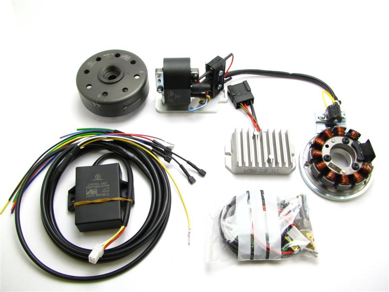 |
Estas partes las debe haber recibido:
* If you want (or need) to renew at your bike the entire wiring, please check:
|
|
Please pay attention: The sensor is not screwed tight on the ground plate, it has to be adjusted by yourself. The stator is not screwed tight on the ground plate. When you mount the ground plate on the crank case, you have to remove the stator. |
|
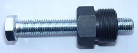 |
Para retirar el nuevo rotor necesita un extractor M27x1.25 (Número de partes: 99
99 799 00 -No
en el alcance de la fuente!-).
ATENCIÓN: ˇAl usar un extractor de garras se sueltan los imanes en el rotor! |
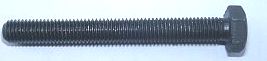 |
To pull the old rotor, you will need a puller tool M10x90 (Número de partes: 89 99 026 00 -No en el alcance de la fuente!-). |
|
|
|
| Make sure your AWO
rests securely on her stand, preferably on an elevated work
bench and that you have good access to the generator side of the engine.
Disconnect your battery and take it out of the motorcycle. Note that should you be installing a 12 volt system, you will either need a 12 volt battery or you use the option of driving without. You will still have to replace all lightbulbs to 12 volt ones however in that case too. The horn may stay at 6 volts. For driving without battery, please observe our information on driving without battery. Technical it is possible to drive your bike without the battery. But consult your local road traffic regulators. |
|
|
|
|
 |
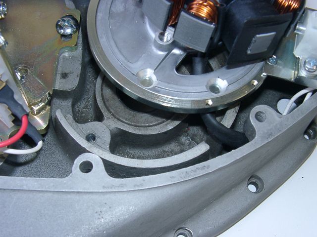
At first replace the old parts:
Loose the 5 hex screws of the generator cover and take it off. Disconnect the cables from your old generator and remove it. Pull off the old rotor with the puller tool (pay attention: the holding screw has a couter-clockwise tap, so you have to screw clockwise for pull off). |
|
|
|
 |
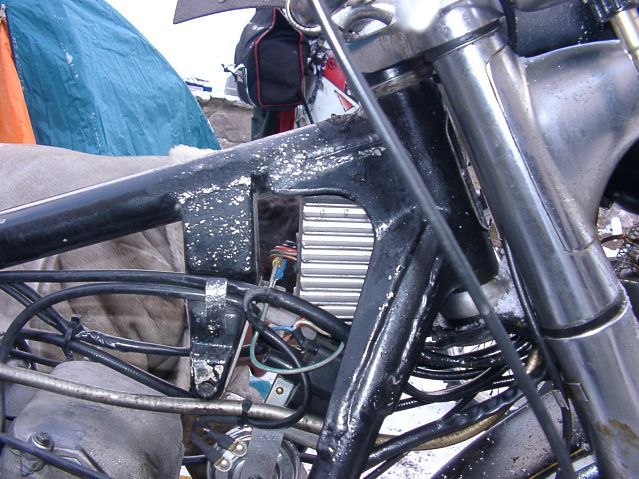
Look in the open lamp casing for the harness (3 wires are coming from the motor
to the ignition lock). It is shown in the picture as
a, c and e. Replace that harness complete.
Now you have to connect the provided short green (mark 1) and blue/red (mark 2) cable pieces (that's only markers). The pictured cables b and d were gone to the old regulator. You will need them no more. You can disconnect and insulate them. |
|
|
|
| Should have your
AWO a regulator in the battery case, remove it. Remove too the cable from
the centre pin of the regulator (F) to the fuse case and cut-off both
other cables (51/61) so short as possible. These are dead wires. If you
be able and willing to pull those cables out of the harness to the motor,
do it.
ATTENTION: Do not remove any other cables from the AWO, especially not this from the battery positive pole to the ignition lock. You will need it further on. |
|
|
|
|
|
At next you have to lead the new harness (with the side with the pre-assembled plugs) through the motor case from the outside to the inside of the motor (push the plugs one after another through). Screw the ignition cable in the new ignition coil, pull over the grommet and lead the cable in the motor too. The ignition coil unit hang loose on the cables, it's not screwed down. |
|
|
|
|
|
Then you have to installate the plugs on the harness. It is now easier -
the unit is not screwed down.
Take a little time for that, rather check it 3 times,
|
|
|
|
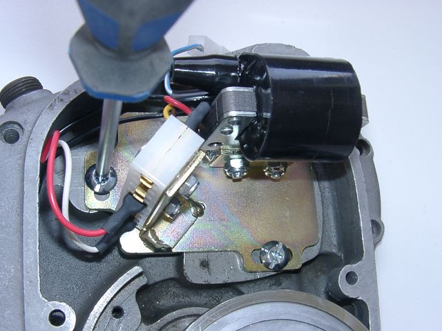
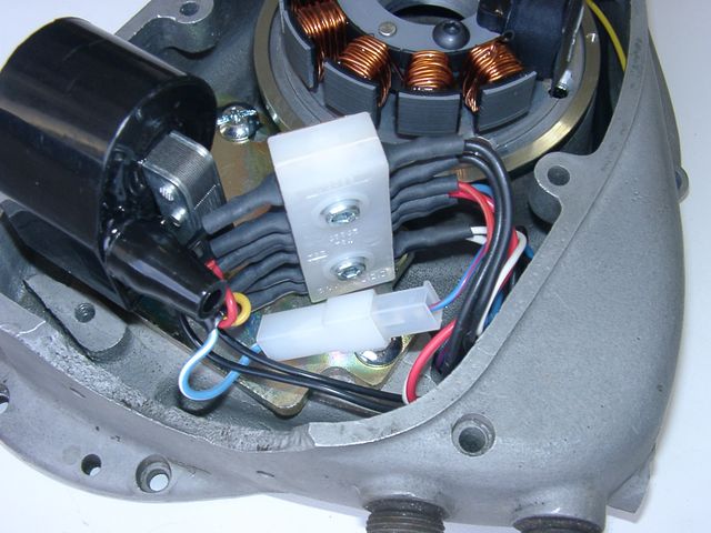
Put a plug on the yellow cable with the pin. Then connect it with the counterpart from the sensor (a yellow cable too). Now you have to put a plug on the pin of the blue/red cable. Plug it together with the blue/white cable from the ignition coil. It is the kill switch cable. Pay attention, don't damage the hanging loose parts: the both unit plates with its assembled parts and the cables with its plugs. |
|
|
|
|
|
Then you have to mount the ignition coil unit. Lay on the paper seal and put on the cover plate with the ignition coil. Screw it on with the 2 screws M6x20. Screw it not tight, so you can shift the plate (if required). The third (upper) screw hole remains idle. |
|
|
|
| Please note: Leave the pre-assembled plug connection of the ignition plate as they are. There is no matter to plug-off them. You risk a mal-connection, loose plugs or even tear-off cables. If you really need to pull out a plug, use a flat-pliers and handle the plug - not the cable!! | |
|
|
|
|
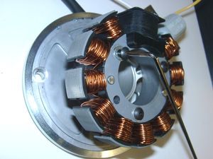
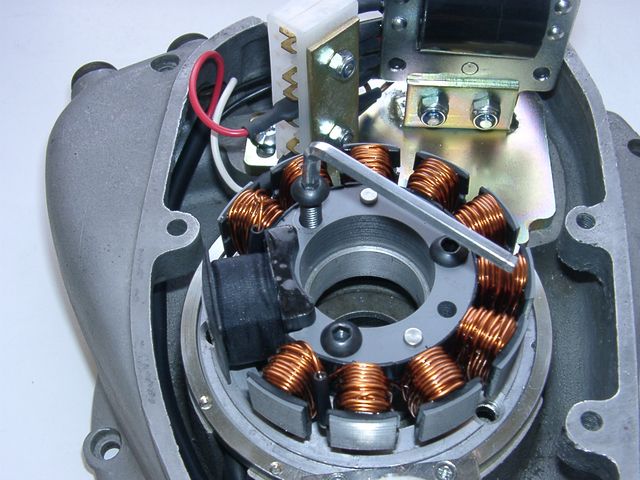
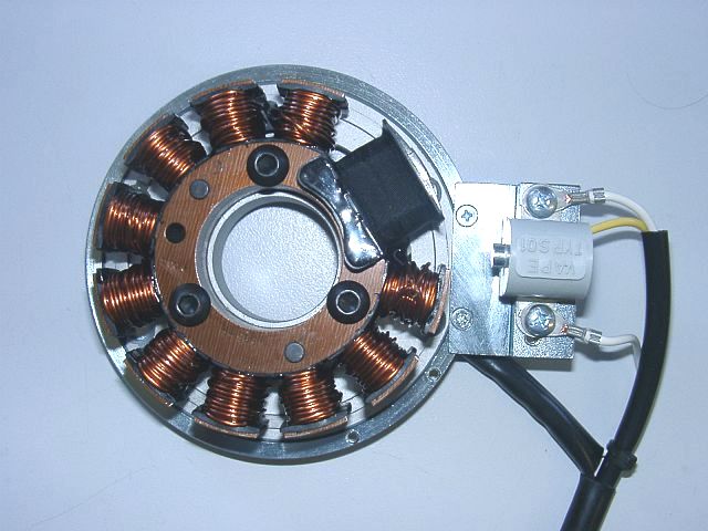
The new stator unit
is pre-assembled, so that its construction is easier to recognise. For the
mounting it has to be partly disassembled.
Pay attention: Do not damage the paint insulation of the coils. Loose the 3 hex screws, they hold the stator on the ground plate. Pull the stator in that way from the plate, so you can handle the 2 mounting holes below. |
|
|
|
|
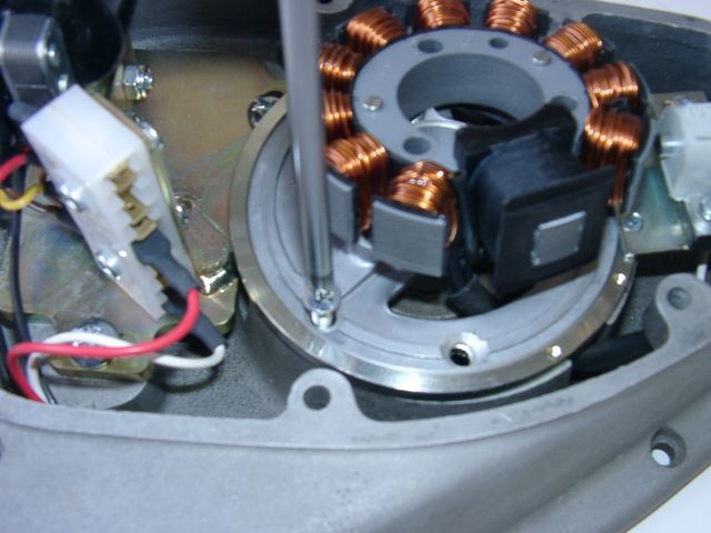
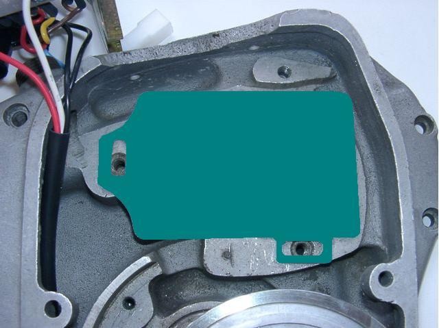
Put the pre-assembled stator plate (steel ring, aluminium plate and sensor) instead of the generator in the crank case. The sensor shows to the ground and the cable shows left upwards to the terminal of the ignition coil plate (if you look from the front on the unit). |
|
|
|
|
Screw down the ground plate (steel ring and inner aluminium plate) on the crank case with the 2 countersunk screws M6x30. The ignition coil unit hang loose on the cables further on. |
|
|
|
|
Now you have to replace the stator on the ground plate. Take care, that no cable is pinched. The coil has to be fitting good on the ground plate - nearly "hearable engage". If is it ain't so, and the coil fits "soft" on the ground plate, is a cable in the way and there is a risk of damaging by contact of the rotor. Screw down the stator with the 3 srews M6. |
|
|
|
|
|
Now pull carefully the ht-cable and the harness (6 cables) afar out of the
case, as they don't trouble the rotor.
Now you can adjust the ignition coil unit with the oblong holes (if required) and tighten the both screws. Do not forget it! |
|
|
|
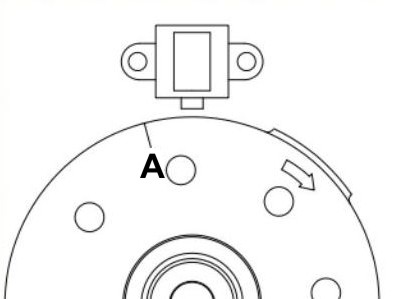 |
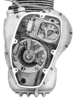
Have a look at the new rotor. You will find on its circumference a protrusion.
This one is the ignition impulse trigger. Our system reads the time the
protrusion needs to pass the sensor and calculates from that how many revs the
crank is doing to set the advance correspondingly.
That's why ignition always happens after the complete protrusion has passed the sensor. In the picture you see the position of the rotor against the sensor at max advance. At our new AWO systems, the rotor has two timing marks. For the ignition adjustment of your AWO use the timing mark that is marked with an "A". |
|
|
|
 |
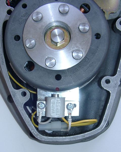
Remove the spark plugs. Place the rotor loosely onto the crank and check that it may move freely
above the statorbase.
Put the new rotor handtight on the crank shaft for turning the shaft. Bring the piston into TDC. At first with the kickstarter (turning by hand) an then, for the fine adjustment, with the new rotor. You have to see the TDC marker (not the marker for the ignition point) concentric in the spy hole. |
| Take the rotor carefully off again without changing the crank's position. Reset it onto the crank in such a way that the ignition mark "A" (resp. the little red marker made by us) aligns with the left edge of the sensor bottom. In that position fasten the rotor carefully (Don't forget to use the washer!) with the left-threaded screw M7x35 provided. | |
|
|
|
|
|
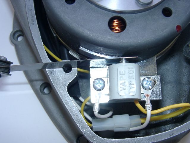
At this time you have to adjust
the gap of 0.4mm between sensor and protrusion. Turn the rotor until
the nose aligns to the sensor. Loose the holding screws of the sensor and
adjust the gap by shifting the sensor.
Don't forget to tighten the screws (also as the gap is O.K. right from the start), we don't tighten fast the screws during the preassembly! |
|
|
|
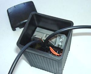
| Now you have to installate the extern parts (rectifier/regulator and the controller). You can place it beneath the tank in the frame triangle or at the sport-version in the side case. For the AWO-Tour, in case of lack of space, we have make the cables any longer. So you can hide the parts in an empty battery case (see our offer). If you like to use this option, you have to saw off one of the both stays. This is not a breach of warranty, as far as you don't saw into the case and you really only cut off the stay. | |
|
|
|
|
|
 |
Take a look to the little blue dip-switch block at the upper flat side of the black ignition advance unit. There are 4 little switches, they are pre-positioned by us. They select the correct ignition advance curve. Please don't change the switch position and check it after the work. All switches has to be OFF (must shown to the digit). Otherwise your system will not or not really function. |
|
|
|
| Now you have to lay the harness on the frame: At first lead the harness upwards the frame beneath the tank. Here splits the new harness. The cable with the 2 wires goes to the lamp, that with the 7 wires goes along the frame backwards (maybe to the earlier position of the battery). Fix the cables with cable fixers. | |
|
|
|
|
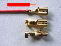
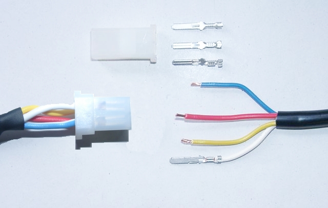
If you have layed the cables and, if necessary, shortened, you have to mount the wire-end-terminals on the cable ends. Please use the included 6.3mm receptacles. Be carefully: the insulation has to be clamped on the rear end (strain relief) and the skinned wire on the front end of the plug. (See picture) After that they will be inserted in plastic plugs. |
|
|
|
|
|
Ignition lock cables:
In the lamp casing you have to change the cable markers (hopefully you have they installed) against the cables of the same colour.
|
|
|
|
 |
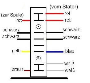
Plug to the advance unit: This relates to the cables red, yellow, blue and white from the generator's wiring. At first you have to cut the cables to the required length (tours or sports) and then to clamp the
terminals.
Following insert the 4 wires (blue, red, yellow and white). Make sure that the terminals engage securely in the housing and that you connect:
|
|
|
|
|
Plug to the regulator/rectifier: First attach the supplied terminals on the green (charge control, only when driving with battery) and the two black
wires.
Then insert the green and the two black wires into the included compact plug. Furthermore the two provided DC output cables (red & brown) will be attached to this plug. (see below!) |
 Seen from the rear (cable) side |
Please ensure that here is color on color - as described below. There should be about the connector no color change (except: green of the wiring to green/red of the
regulator/rectifier)!
Attention: Any confusion between plus and minus (with the DC versions) leads to immediate destruction of the regulator. This will not constitute a warranty case as it is negligence! One can recognize a burnt regulator mostly by its sharp smell. |
|
|
The new regulator/rectifier has a compact plug with 6 positions, of which one is not used. A female plug cover fitting to this plug is delivered. Into this female plug you have to insert the following wires (which have terminals that snap into the plug): |
| The two black cables leading from the generator ... |
... connect to pins 1/4 of the new regulator (from there equally black wires lead inside the unit). It does not matter which wire connects to which of the both terminals (1/4) as they carry alternating current. |
| The new brown cable with the round eye terminal ... |
... connects pin 3 of the regulator unit (from there equally a brown wire goes inside the unit) with the negative pole of the battery or (in case you drive without battery) to ground (chassis). |
|
The new red cable with the round eye terminal ... Take care: |
... connects to pin 5 of the new regulator (from there equally a red wire goes inside the unit). Here your regulated positive voltage comes out to connect to battery plus, or (in case you drive without battery) to the voltage input terminal of the main switch (ignition lock, German bikes: pin 51/30). |
| Make sure that you have a 16A-fuse between battery and vehicle circuitry. | |
|
The green/red wire at pin 6 of the new regulator ... Remark: |
... is for the charge control light. You connect there the wire that formerly did run from the control light to the original regulator. Sure that this control only functions with a battery present. Should you drive without battery but still connect the wire, you will see that the light glows even as the generator generates voltage. So without battery, do not connect it. |
| Please check once again that there is no color change over the connectors (plugs) (except as
described).
If you want to drive without battery, then the brown wire is connected to ground, best to the place where the former minus of the battery were connected. The red wire is connected to the cable that previously went from the battery to the ignition switch. If you want to drive with battery, connect the brown wire to "minus" of the battery and the red wire to "plus" additional to the stock cables. Do not disconnect these stock cables - it's the connection to the electrical consumers of your motorcycle. Finally - and before installing the battery and before the first kickstart - please re-check carefully all connections and fitments against the wiring diagram (see here). Do check battery and light bulbs for correct voltage (12V). Should something not work, please consult our trouble-shooting guide on our homepage. As a first step disconnect the blue wire from the coil and re-test. |
|
|
|
|
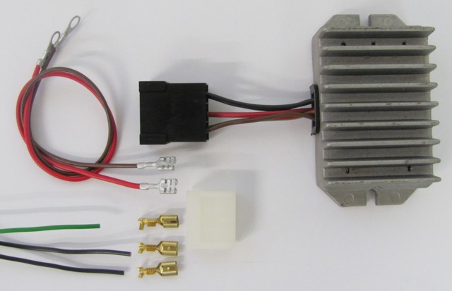
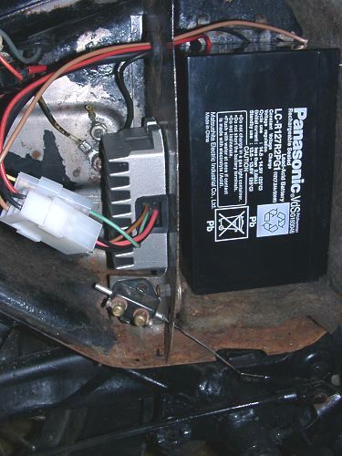
| At next will be the rectifier/regulator (it is pre-assembled on a mounting plate) installed under the rear tank mounting. For that unscrew the nut on the transverse stay (spanner 13). Put on the new mounting plate with the rectifier/regulator (the cooling ribs shown to the top) and fasten it with the nut and a washer. | |
|
|
|
|
Importantes llamadas de atención de seguridad y de funcionamiento: |
|
|
# |
Haga caso a las llamadas de atención de seguridad e imposiciones reglamentarias del fabricante del vehículo y del oficio de vehículos. |
|
# |
ˇCentrales de cebado producen alta tensión! ˇCon nuestras bobinas de ignición hasta 40.000 voltio! ˇEsto no sólo puede hacer mucho dańo si lo utiliza siendo incauto, sino también puede causar problemas para el corazón! Por eso preserve siempre la distancia de seguridad al electrodo y a cables de alta tensión abiertos y en el test siempre pulse con fuerza el macho de enchufe de la bujía de encendido (enchufes de bujía) con un objeto aislador a la masa para desviar seguramente el voltaje. |
|
# |
Después de la instalación, por favor compruebe el estado fijo de los tornillos de apoyo del estator y (si existente) del senor. Si las piezas se aflojan, se surgirá la destrucción. ˇSólo apretamos los tornillos en el preénsamblaje sueltamente! |
|
# |
Dele primero por lo menos una oportunidad al dispositivo recién instalado de encenderse, antes de empezar de medir y de comprobar todo si funciona verdaderamente. O peor: hacer modificaciones directamente sin haber encendido la instalación. Todas nuestras piezas están comprobados antes de la entrega. Además no van a tener suerte medirlas. Por favor, deje la medida de las piezas electrónicas (entre ellas la bobina de encendido con excepción de su salida de alta tensión). ˇAriesga la destrucción y no van a llegar a resultados usables! Piense en esto: también pueden ser el carburador y sobre todo los soportes de bujía y las bujías (por lástima también las completamente nuevas) si el motor no va directamente (regularmente, después de la instalación de Lima, también sus regulaciones deberían ser cambiadas). Si el dispositivo no va directamente, sobre todo compruebe las conexiones de masa, pone por lo menos para el test un nuevo cable de toma de tierra de nuestro regulador directamente al motor. |
|
# |
Si tiene un dispositivo con bobina de encendido doble, por favor tenga en cuenta algunas particularidades de esta bobina. El encendido sólo funciona corectamente si ambas bujías están conectadas con la bobina. Entonces no puede quitar una bujía sólo para testar. Es porque cada salida carga masa por la bujía de la otra salida. Si quiere testar seguramente sólo un lado hay que poner la otra salida de bobina sobre masa. |
|
# |
La chispa de centrales de interrupción clásicas tiene con 10.000 voltios sólo una energía pequeńa y es por eso amarilla y gorda. La chispa de nuestras centrales es una chispa de alta energía con hasta 40.000 voltios y es por eso muy concentrado y azúl, que le hace menos buen visto. Además esta chispa está producida sólo con un número de revoluciones pedaleado con el pedal de arranque. Sólo estirar el pedal de arranque con la mano no produce una chispa. |
|
# |
Nunca hacer la soldadura de arco eléctrico en la bicicleta sin desconectar completamente todas las partes que contengan semiconductores (bobina de encendido, regulador de antelación) estator y el rotor no es necesario que se deban tomar fuera. |
|
# |
La electrónica es sensible al polo falso. Compruebe siempre después de una intervención al sistema la conexión correcta de la batería y el cableado correcto. Polos falsos y cortocircuitos destruyen el regulador y la bobina de encendido. Normalmente hay que conectar en el cableado siempre color con color. Excepciones están mencionadas explícito en la instrucción. |
|
# |
Atienda a no romper los imanes mientras la instalación del rotor. Evite la influencia mecánica y directa al rotor. Para el transporte de la Lima nunca ponga el estator en el rotor, atienda a las indicaciones para el envío (embalaje). |
|
# |
No utilice enchufes de bujía con una resistencia a más de 5 kOhmios. Recuerde que enchufes de bujía envejiecen y que intensifican con eso su resistencia. Si un motor sólo arranca en estado frío con gran seguridad la razón es un enchufe de bujía defecto. No utilice cables llamados aumentando el encendido (por ejemplo Nology). |
|
# |
Engrase el rotor un poco por fuera, sino va a corroerse rápidamente en el entorno agresivo (que no hace dańo pero parece muy feo). |
|
# |
No utilice nunca un para extraer el rotor un extraido de forma de garras o un martillo. Con estos se podrían aflojar los imanes. Siempre sólo un extraido de tornillo solo M27x1.25 (mire las instrucciones de instalación). |
|
# |
Si vuestro vehículo no está utilizado por un poco más tiempo, debería desconectar la batería (si existente) para evitar una descarga lenta por los diodos del rectificador de corriente. Pero también va a darse cuenta de una descarga de la batería después de algún tiempo aunque habrála desconectado, eso es normal. |
|
# |
Por favor presta atención a estas indicaciones pero tampoco dejese confundir. Antes de usted, miles de clientes ya han instalado nuestros dispositivos con éxito. ˇMucho éxito y que se divierte conduciendo! |