Powerdynamo brings new ignition & light
to your vintage motorcycle
![]()
![]()
|
|
Powerdynamo brings new ignition & light |
|
|||
|
|
|||||
|---|---|---|---|---|---|
| Assembly instructions for System 71 06 599 00 |
Version 26.03.2014 |
|
If you can install and time a stock ignition and
possess basic mechanical skills, you can install a Powerdynamo! |
|
| Powerdynamo can not monitor the compliance to those instructions, nor the conditions and methods of installation, operation, usage and maintenance of the system. Improper installation may result in damage to property and possibly even bodily injury. Therefore we assume no responsibility for loss, damage or cost which result from, or are in any way related to, incorrect installation, improper operation, or incorrect use and maintenance. We reserve the right to make changes to the product, technical data or assembly and operating instructions without prior notice. | |
|
|
Please read these
instructions fully and carefully before starting work on your motorcycle Please bear in mind that any modification of the material as well as own repair attempts which have not been agreed with Powerdynamo may result in a loss of warranty. Do not cut off wires. This leads to a loss of reverse polarity protection and often results in damage to electronics. Also, please take note of the information provided on the information page for this system. Check that what you have bought really corresponds to the motorcycle you have. Wrong ignition settings may damage your engine and even hurt you during kickstart (violent kickbacks). Be careful during the first test runs. If needed change settings to safer values (less advance). During assembly check carefully that the rotor (flywheel) does not touch the stator coils or anything else, which may happen due to various circumstances and lead to severe damage. |
| Designated use This system is designated to replace stock dynamo/alternator & ignition systems in vintage and classic motorcycles whose engine characteristics have not been modified aftermarket. This system is not a tuning system and it will not bring significant increases in engine output. It does however significantly enhance roadworthiness and comfort by offering better lighting, better function of side indicators and horn and, compared with the aging stock systems, increased reliability. As our system does not tamper with engine characteristics it does not increase emission of gaseous pollutants and noise. In most cases emission of pollutants should even be reduced due to better combustion. If used as designated the system therefore will not normally infringe the existing legal status of the motorcycle (this statement is valid for Germany, for other countries, please check locally against your road licensing regulations). This system is not suitable for use in competition events. If used other than the designated way, warranty will be voided and it might well be that you do not obtain the desired results or, worst you loose legal roadworthiness. The charging system is only suitable for use with rechargable 12V (6V systems 6V) lead-acid batteries with liquide electrolyte or sealed lead-acid batteries, AGM, Gel. It is not suitable for use with nickel-cadmium, nickel-metal-hydride, lithium-ion or any other types of recharchable or non rechargable batteries. This is a replacement system and not a copy of the stock material. The parts in this system therefore look different and might fit differently (notably ignition coil and regulator) requiring some adaptation by you. |
|
| During assembly imperatively start with assy of engine based parts to see that those really fit before you start fitting the external parts. In many cases customers assemble those first and thereby often modify them in breach of warranty which renders them unfit for renewed sale. Replacing old ignition systems is not a matter of taking something from a supermarket shelf as there have been very many types, versions and possibly unknown aftermarket modifications which harbour plenty of room for error. | |
| Our systems are NOT tested for use with third party electronic devices (such as GPS, mobile phones, LED lighting etc)and may cause damage to such parts. Possibly existing electronic tachometers will not work with the new system. Read our information for suitable solutions. Possibly existing safety switches and electronic valve controls are not supported. It might be that your motorcycle was originally equipped with an ignition that did limit top speed for legal reasons. The new system does not have such a facility, so check your legal situation beforehand. | |
| If you have no expertise for the installation have it done by an expert or at a specialist's workshop. Improper installation may damage the new system and your motorcycle, possibly even lead to bodily harm. | |
| Before you order a system, please check whether a puller
tool for the new rotor is included in the kit. If not,
better order it at the same time. You might want to order light bulbs,
fuse, horn,
flasher
unit etc. Never use anything other than the recommended puller tool to pull the new rotor again. Damage to the rotor as a result of use of other tools or methods is not covered by warranty. |
|
| The rotor is sensible to blows (including during transport). Before assembly, please always check for damage (on rotor without magnet plastification try to push the magnets aside with your fingers). After impact the glued in magnets might have broken loose, sticking to the rotor solely by magnetic force, so that one does not notice right away. During engine run the damage would be considerable. Before placing the rotor onto the engine, please make sure that its magnets have not collected any metal objects such as small screws, nuts and washers. That equally would lead to severe damage. | |
|
|
If you have access to the Internet, best view those instructions online. You get larger and better pictures by clicking onto them and possibly updated information. System list at http://www.powerdynamo.biz |
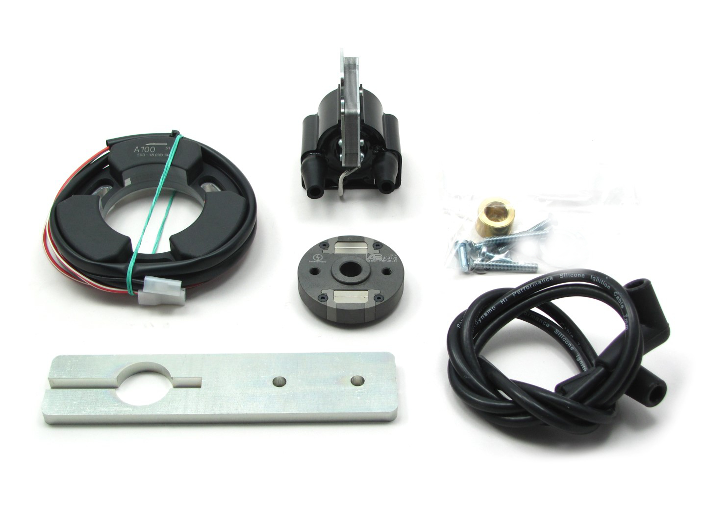 |
You should have received those parts:
|
|
|
|
 |
|
|
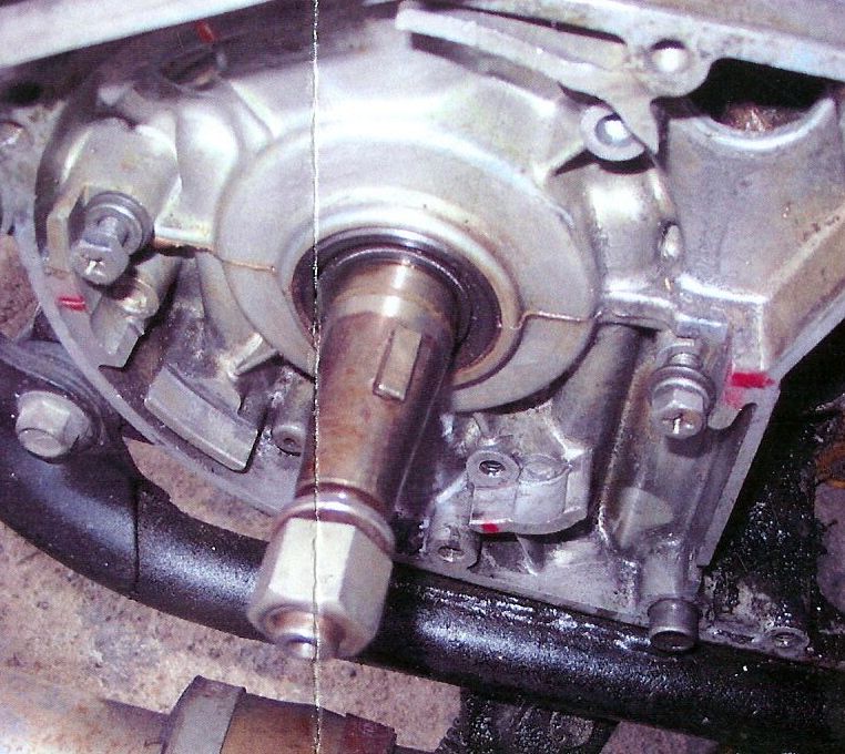
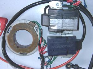
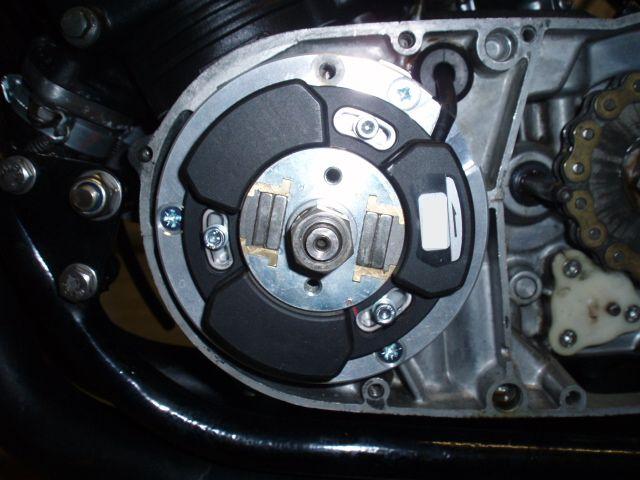
Make sure your bike rests securely on its stand, preferably on an elevated work
bench and that you have good access to the generator side of the engine.
Take-off your old ignition system (different types are possible, in the picture above you can see a Femsa) and eventually all adapter plates and the old ignition coil. Pull the rotor off, you will need a puller screw for this. Take the woodruff key from the crank. You will not need it anymore. Please do not forget to do so, otherwise you will have trouble later on the assembly. (Remark: This woodruff key does not actually hold your rotor on the shaft, this is done by the cone. It simply guides to the correct setting which will now be otherwise achieved.) |
|

|
Place the adapter plate onto the engine. Wire recess will need to show into the direction of ca 2 o�clock. Fix it with the 3 supplied countersunk screws M6. Place the stator ring onto the adapter. Fasten it with the supplied 3
screws M5 and the washers.
|
|
|
|
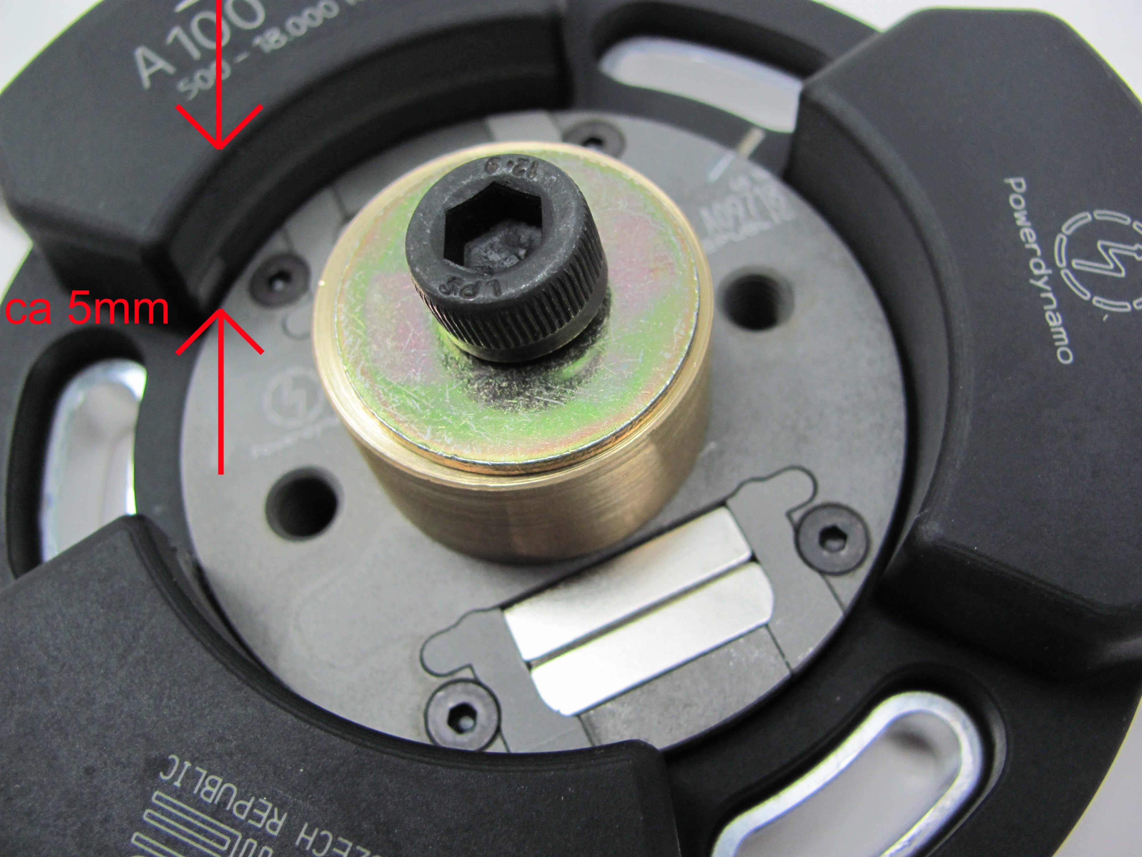 |
Place the adapter onto the engine. The wire opening of the adapter will show to
about 2 o'clock. Screw the adapter down with the 3 countersunk screws M6x25.
Put the stator onto the adapter. The wire has to be in the adapter opening.
Screw the stator down with the 3 hex screws M5, not forgetting a washer each. Picture shows earlier shaft version. The ca 5mm are however same. |
|
|
|
|
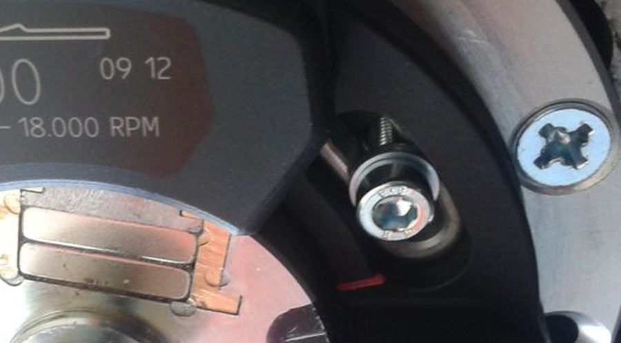
To be able to make use of the long holes to modify timing, set the screws into the middle position of those oblong holes. |
|
|
|
|
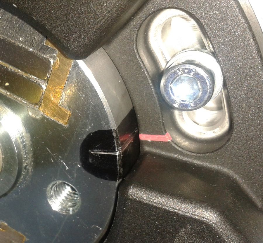
Remove spark plugs. Set one (no matter which one) of the 2 pistons into
ignition position. (Any, as the system will fire both cylinders at the
same time, which means you get a so called wasted spark into exhaust
something not uncommon and effectively harmless.) Whilst the crank remains in ignition position, carefully place the rotor onto it, in such a way that the small red marking on the rotor aligns with the red line on the inside of the stator. Take care not to change this position of the crank during that operation. In this position the engine should run, but probably will not be set to accurate and safe values. Use a stroboscope to finally time. Not suitable settings may damage the engine and possibly even harm your health. Have settings controlled by a specialist mechanics shop. Take extra care at first starts. |
|
|
|
|
Fasten rotor with the stock nut, not forgetting to place the washers
and spacers below nut. |
|
|
|
|
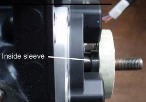
Should your rotor now sit well above the stator as shown here, you have used the wrong system. You will need in this case system 71
13 599 00 |
|
|
|
 |
For turning the rotor and stabilizing when fastening, use the enclosed tool as shown. Picture shows earlier shaft version |
|
|
|
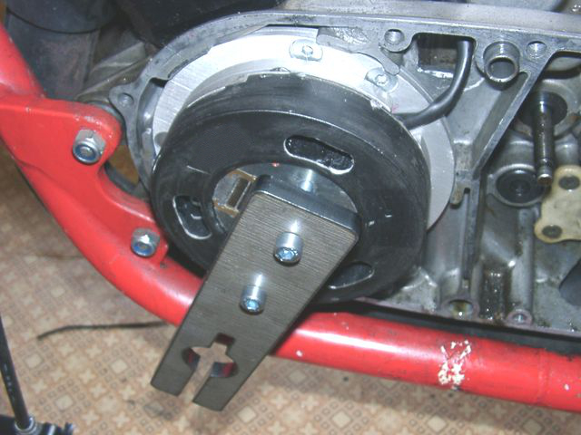 |
The same tool can be used to pull off the rotor again. If the crank shaft
don't reach over the rotor to get pressed off, please use
some spacer, best a larger steel ball. |
|
|
|
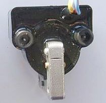
| Fasten the new twin ignition coil on the frame of your bike and screw the both ht-cables in. Connect the both plugs from the stator wire on the ignition coil terminal. These contacts have different dimensions, so you can't push it on wrong. The ignition coil is not only a transformer, but it included also a capacitor discharge ignition. So never mix those wires up and never connect the coil to something else. | |
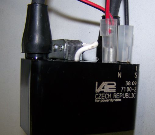 |
The red/white cable (6.3mm plug) is good for the ignition voltage, the black cable (4.2mm plug) for the pulse. The red/white cable branches - it goes to the kill switch for cut-off the system. Connect the metal core of the ignition coil to solid electrical ground. It's not enough to screw it down to the painted frame. Best use a extra ground wire there. |
|
|
|
|
Connect the parts as shown here: 52sport |
|||
|
This is very simple. The cable from
the stator has 2 plugs in different sizes.
The ignition coil has 2 suitable terminals. Put the plugs onto the
suitable terminals. Confusing the plugs will destroy the coil! The free end of the small sideways connected wire is the wire for the kill switch. When that is connected to ground, ignition will stop. Here you connect your OFF-switch which closes against ground when activated. extremely important is to fit a ground wire securely connecting the metal core
(holder frame) of the coil to engine ground (not to frame as
contact between engine and frame is never good!). |
|||
|
|
|||
|
Screw the high tension cables into the ignition coil and place the rubber
seals over the exits. It's more easier if you do that before mounting the
coil. Please do use the cable arriving with the pack and not any old
cables.
You will do yourself a favour to treat your bike to new spark plugs and spark plug sockets (preferably some between 0-2kOhm). Plenty of problems are to be traced back to "apparently good" (even completely "brand-new") sparks plugs, terminals and cables. Do not use spark plugs with an intern suppression resistor. NGK (e.g.) offered such spark plugs coded with an "R" (for resistor). Further, please do not use any spark amplifying cable, such as "Nology supercables" or "hot wires". This will disturb the system and possibly damage it. |
|||
|
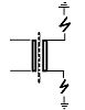
In our twin outlet coils both ends of the secondary go to spark plugs.
Typical resistance between both exits is 6.2kOhm. Both exists fire at the same time (as many twin systems do). Sparks will be polarised however at a 180 degrees difference which might manifest when you strobe it and which can show with some amount of carbonisation at the spark plug getting the positive spark. This is however not a serious problem and, unfortunately, it can not be helped.. |
||
|
Ignition will only work correctly if both plug terminals are connected.
You may not test one side with the other open (not sitting on the mounted
spark plug). This is because (effectively) each exit uses ground from the
other. That means also that both plugs are working in serial, adding
resistances, so better use low resistance spark plug (resistor) sockets
and make sure they are good (if in doubt, measure resistance on a hot
socket (warm it up before measuring).
Is the flow from ground of one side via spark plug there, via coil, to the other spark plug and its ground interrupted you get no spark - on neither side. If you really want to test only one side, put the HT wire of the other to ground (earth it) than it will work. The use of 2 individual ignition coils is not possible on this system. Sometimes a coil deprived of its ground from the other side searches for a substitute - with some solid fireworks around it to the chassis. |
|||
|
Finally - and before installing the battery and before the first kickstart - please re-check carefully all connections and fitments against the wiring diagram. Please don't depend on the frame as the earth-connection. Varnish, oil and dirt prevent often a good contact! Should something not work, please consult our trouble-shooting guide on our homepage. As a first step disconnect the blue wire from the coil and re-test. |
|||
|
Please note: The crankshaft speed needed to get the system sparking
is with about 500 revs/min quite high. If you simply turn the rear wheel of your
lifted vehicle to check spark,
you will not get any. You need fast kickstart action or better still push-starting the bike. |
|||
|
|
Important safety and operating information for sports systems of type 71 00 |
| The material has been exclusively made for sports purposes and is NOT destined for use on public roads! | |
|
# |
Safety first! Please observe the general
health and safety regulations motor vehicle repair (MVR)
as well as the safety information and obligations indicated by the
manufacturer of your motorcycle. The timing marks on the material are for general guidance only during first installation. Please check after assembly by suitable means (stroboscope) that settings are correct to prevent damage to the engine or possibly even your health. You alone are responsible for the installation and the correctness of settings. |
|
# |
Ignition systems generate high tension! With our material right up to 40.000 Volts! This may, if handled carelessly, not only be painful, but outrightly dangerous. Please do keep a safe distance to the electrode of your spark plug and open high tension cables. Should you need to test spark firing, hold the spark plug socket securely with some well insulating material and push it firmly to solid ground of the engine block to earth the output. |
|
# |
After installation, please check tightness of all screws. If parts get loose during run, there will be inevitably damage to the material. We pre-assemble screws only loosely. |
|
# |
Give the newly installed system a chance to work, before you start
to check and test values, or what is worse is to apply changes to
customize the firing point before running the system. Our parts have been checked before delivery to you. You will not be able to check much anyway. At any rate do refrain from measuring the electronic components (both stator and ignition coil). You risk severe damage to the inner electronics there. You will not get any tangible results from the operation anyway. Bear in mind that also your carburetor and your spark plugs and spark plug sockets might be the reason for malfunction (even if absolutely new). The general experience with our systems is that the carburetor will have to be re-adjusted to lower settings. Should the system not start after assembly, first disconnect the blue cut-off wire directly at the ignition coil (or in some cases advance unit) to eliminate any mistake in the cut-off circuitry. Check ground connections carefully, better put an additional wire between engine block and metal frame of the ignition coil. |
|
# |
The shaft speed needed to start ignition is relatively high with about 500revs/min. Simply turning the lifted rear wheel will not produce a spark. You need rapid kick-starter movement or better still push-start. |
|
# |
There are systems destined for clockwise and there are
systems destined for anticlockwise run of the crankshaft. Confusing the 2
senses will mean you have no spark. You may check for what sense your
system has been made by the colour of its wires. |
|
# |
The spark of classic, points based ignition systems has with only about 10,000 Volts little energy and looks therefore yellow and bulky (hence well visible). The spark from our system is a high energy spark with up to 40,000 Volts and is therefore very sharp (needle thin focused) in form, and blue in colour, which makes it not well visible. Furthermore you get spark only at kick-start operated speeds and not by pushing the kick-lever down slowly with your hand (as you might get on classic systems). |
|
# |
Systems using a twin outlet ignition coils have a few perculiarities. Please observe that during tests on one side, the other has either to be connected to an fitted spark plug or securely earthed. Otherwise there will be no spark on either side. |
|
# |
Never do electric arc welding on the bike without completely disconnecting all parts containing semiconductors (ignition coil, regulator, advance) stator and rotor need not be taken off. Never use copper putty on spark plugs. |
|
# |
When connecting the ignition coil double check that you put the wires to the correct pins. (One is smaller). If you confuse them, the high tension for the condenser charge will kill the input switch |
|
# |
Do not use spark plug sockets with a resistance of more than 5kOhm. Better use 1 or 2kOhm ones. Bear in mind that spark plug sockets do age and thereby increase their internal resistance. Should an engine start up only when cold, a defective spark plug socket and/or spark plug is very probably the cause. In case of problems check high tension cables too. Never use carbon fibre HT-cables. Never use so called "hot wires", never use resistor spark plugs on this system, it will hamper starting. |
|
# |
It is a good idea to cover the rotor in a thin layer of oil to reduce the risk of corrosion. |
|
# |
Please do observe these remarks, but at the same
time, don't be afraid of the installation process. Remember, that before you, thousands of
other customers have successfully installed the system. Enjoy driving your bike with its new electric heart! |
|
|