Powerdynamo brings new ignition & light
to your vintage motorcycle
![]()
![]()
![]()
![]()
|
|
Powerdynamo brings new ignition & light |
|
|||
|
|
|||||
|---|---|---|---|---|---|
| Installationsanleitung f¸r System 70
04 799 2Zy y = 2 (f¸r Mutter M12) y = 4 (f¸r Mutter M14) |
Version 03.10.2009 |
|
If you can install and time a stock ignition and
possess basic mechanical skills, you can install a Powerdynamo! |
|
| Powerdynamo can not monitor the compliance to those instructions, nor the conditions and methods of installation, operation, usage and maintenance of the system. Improper installation may result in damage to property and possibly even bodily injury. Therefore we assume no responsibility for loss, damage or cost which result from, or are in any way related to, incorrect installation, improper operation, or incorrect use and maintenance. We reserve the right to make changes to the product, technical data or assembly and operating instructions without prior notice. | |
|
|
Please read these
instructions fully and carefully before starting work on your motorcycle Please bear in mind that any modification of the material as well as own repair attempts which have not been agreed with Powerdynamo may result in a loss of warranty. Do not cut off wires. This leads to a loss of reverse polarity protection and often results in damage to electronics. Also, please take note of the information provided on the information page for this system. Check that what you have bought really corresponds to the motorcycle you have. Wrong ignition settings may damage your engine and even hurt you during kickstart (violent kickbacks). Be careful during the first test runs. If needed change settings to safer values (less advance). During assembly check carefully that the rotor (flywheel) does not touch the stator coils or anything else, which may happen due to various circumstances and lead to severe damage. |
| Designated use This system is designated to replace stock dynamo/alternator & ignition systems in vintage and classic motorcycles whose engine characteristics have not been modified aftermarket. This system is not a tuning system and it will not bring significant increases in engine output. It does however significantly enhance roadworthiness and comfort by offering better lighting, better function of side indicators and horn and, compared with the aging stock systems, increased reliability. As our system does not tamper with engine characteristics it does not increase emission of gaseous pollutants and noise. In most cases emission of pollutants should even be reduced due to better combustion. If used as designated the system therefore will not normally infringe the existing legal status of the motorcycle (this statement is valid for Germany, for other countries, please check locally against your road licensing regulations). This system is not suitable for use in competition events. If used other than the designated way, warranty will be voided and it might well be that you do not obtain the desired results or, worst you loose legal roadworthiness. The charging system is only suitable for use with rechargable 12V (6V systems 6V) lead-acid batteries with liquide electrolyte or sealed lead-acid batteries, AGM, Gel. It is not suitable for use with nickel-cadmium, nickel-metal-hydride, lithium-ion or any other types of recharchable or non rechargable batteries. This is a replacement system and not a copy of the stock material. The parts in this system therefore look different and might fit differently (notably ignition coil and regulator) requiring some adaptation by you. |
|
| During assembly imperatively start with assy of engine based parts to see that those really fit before you start fitting the external parts. In many cases customers assemble those first and thereby often modify them in breach of warranty which renders them unfit for renewed sale. Replacing old ignition systems is not a matter of taking something from a supermarket shelf as there have been very many types, versions and possibly unknown aftermarket modifications which harbour plenty of room for error. | |
| Our systems are NOT tested for use with third party electronic devices (such as GPS, mobile phones, LED lighting etc)and may cause damage to such parts. Possibly existing electronic tachometers will not work with the new system. Read our information for suitable solutions. Possibly existing safety switches and electronic valve controls are not supported. It might be that your motorcycle was originally equipped with an ignition that did limit top speed for legal reasons. The new system does not have such a facility, so check your legal situation beforehand. | |
| If you have no expertise for the installation have it done by an expert or at a specialist's workshop. Improper installation may damage the new system and your motorcycle, possibly even lead to bodily harm. | |
| Before you order a system, please check whether a puller
tool for the new rotor is included in the kit. If not,
better order it at the same time. You might want to order light bulbs,
fuse, horn,
flasher
unit etc. Never use anything other than the recommended puller tool to pull the new rotor again. Damage to the rotor as a result of use of other tools or methods is not covered by warranty. |
|
| The rotor is sensible to blows (including during transport). Before assembly, please always check for damage (on rotor without magnet plastification try to push the magnets aside with your fingers). After impact the glued in magnets might have broken loose, sticking to the rotor solely by magnetic force, so that one does not notice right away. During engine run the damage would be considerable. Before placing the rotor onto the engine, please make sure that its magnets have not collected any metal objects such as small screws, nuts and washers. That equally would lead to severe damage. | |
|
|
If you have access to the Internet, best view those instructions online. You get larger and better pictures by clicking onto them and possibly updated information. System list at http://www.powerdynamo.biz |
|
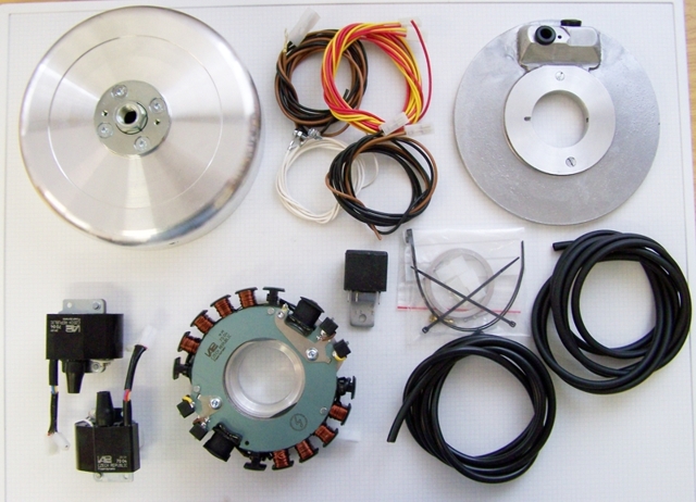
Diese Teile sollten Sie erhalten haben:
|
|
|
|
|
Lösen sie nun alle Kabel an Ihrer alten Lichtmaschine und entfernen Sie diese. Entfernen Sie die Paþfeder auf der Kurbelwelle, der in die Nut der alten Schwungscheibe ging. Keine Angst, der hat keine Haltefunktion, er sollte nur zur Z¸ndeinstellung f¸hren. Vergessen Sie die Paþfeder zu ziehen, geht sp‰ter der Rotor nicht auf die Welle und Sie m¸ssen den Stator erneut abbauen um an die Paþfeder zu kommen. |
|
|
|
|
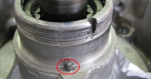
Setzen Sie die hintere Adapterplatte auf den Motorblock.
Dabei auf den kleinen Arretierstift am Motorblock achten.
|
|
|
|
|
Es empfiehlt sich dabei zuvor die Kabel durch die beiden
Kabelt¸llen zu f¸hren. Das betrifft die beiden Kabelstr‰nge zu
den Z¸ndspulen, das Massekabel und das Stromkabel.
Die Kabelstr‰nge sollten mit einem Kabelbinder als Zugentlastung gesichert werden. Pr¸fen Sie aber vor dem festziehen welche freie Kabell‰nge benˆtigt wird! |
|
|
|
|
Der elektrische Anschluþ ist von der Sache her recht einfach (wenn
auch etwas fummelig). Den technischen Schaltplan finden Sie hier. 1 und 2 sind die Kabel zu den Z¸ndspulen Kabel 3 ist das Stromkabel welches zum Regler gef¸hrt wird. Hier gibt es nur einen Einzelkontakt. Kabel 4 ist das Massekabel welches auf den Stator verschraubt wird. |
|
|
|
| Die beiden Z¸ndspulen und der Regler m¸ssen leider auþerhalb des Motorblocks untergebracht werden. In Abh‰ngigkeit von der konkreten DKW kann das unter dem Tank, unter der Abdeckung des fr¸heren Dynamos auf der linken Seite oder in einem leeren Batteriegeh‰use erfolgen. | |
|
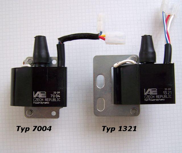
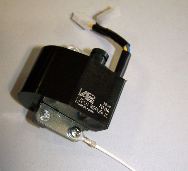
Wir bieten 2 verschiedene Z¸ndspulen an, die sich in der physischen
Form des Haltebleches unterscheiden.
F¸r eine Montage unter dem tank z.B: kˆnnte die Variante 1231 mit dem mit Schraublˆchern versehenen Halteblech durchaus interessant sein. Elektrisch und in den Steckern sind beide Spulen gleich, wobei aber das bei der 7004 gelb ausgef¸hrte Kabel bei der 1321 weiþ ausgef¸hrt ist. |
|
|
|
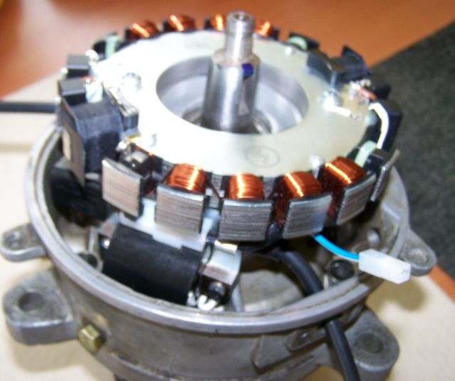 |
Stecken Sie jetzt die neue hintere
Abdeckplatte auf den Motor. Achten Sie darauf das diese korrekt
aufsitzt - es gibt da einen kleinen Sicherungsstift.
|
|
|
|
| Den Distanzring einlegen ohne den die DKW Mutter sonst keinen Halt am Stator findet. | |
|
|
|
 |
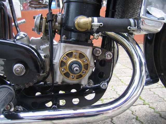
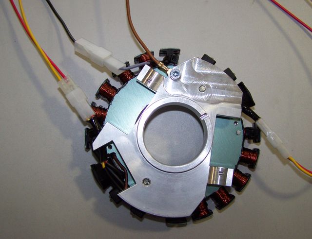
Verschrauben Sie die Stator(Spulen)einheit mit der DKW Mutter (Rechtsgewinde!). Dazu das originale oder unser Ersatzwerkzeug nutzen, nicht mit Hammer und Schraubenzieher! Wir bieten einen solchen Schl¸ssel an (Teil 70 04 799 99). |
|
|
|
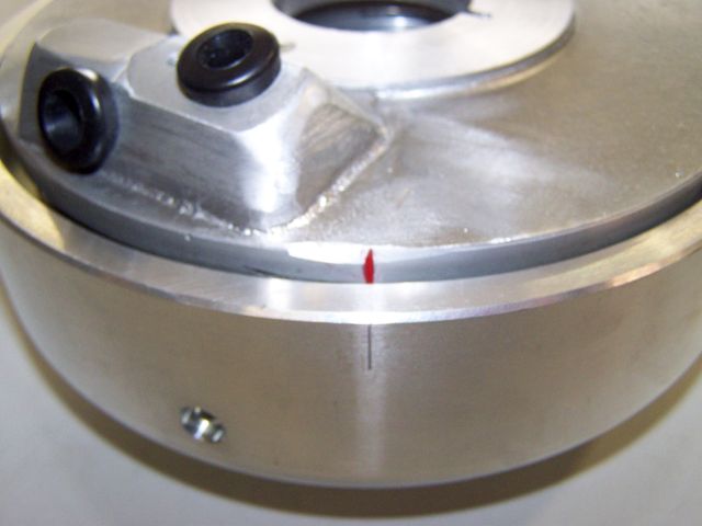 |
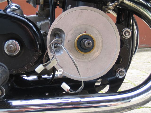
Sehen Sie sich die hintere Abdeckung an. Auf dem Umfang gibt es eine
kleine rote Linie.
Sehen Sie sich den Rotor an, auf seinem Umfang gibt es eine eingepresste Linie. Beides sind Z¸ndmarken. Sie stehen im Moment der Z¸ndung von Zylinder 1 ¸bereinander. 180 Grad sp‰ter folgt Zylinder 2. |
|
|
|
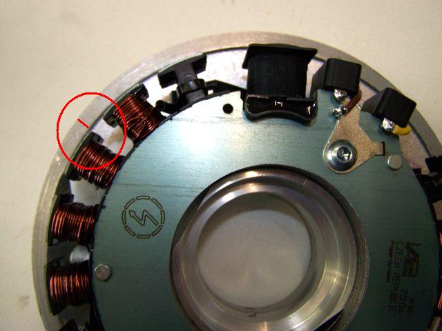 |
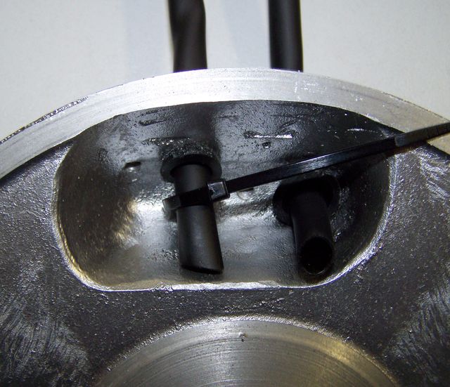
Sollte diese Marke einmal nicht mehr richtig sichtbar sein kˆnnen Sie diese wieder wie hier gezeigt neu anbringen. Sie muss auf Hˆhe der rechten ‰uþeren kante der 2. kupferfarbenen Spule links von den schwarzen Spulen angebracht werden. |
|
|
|
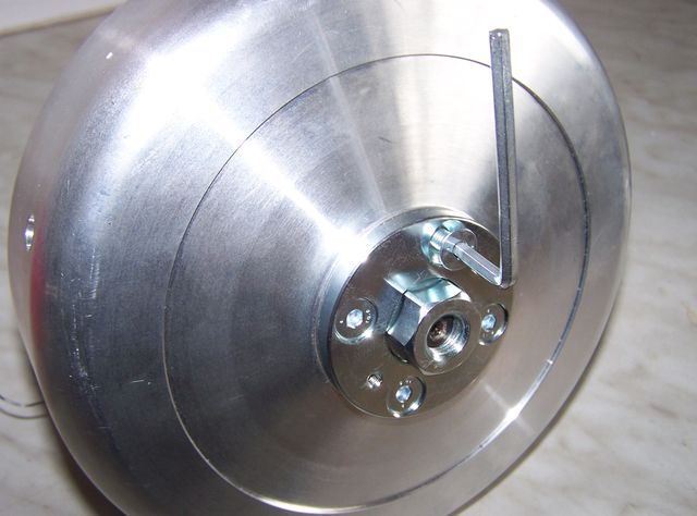
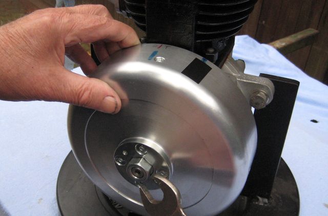
| Um die Z¸ndung einzustellen m¸ssen Sie
zun‰chst (bei herausgeschraubter Kerze) die Kurbelwelle in
Z¸ndposition bringen. Das sollten ca 4mm vor OT sein. In dieser
Stellung der Welle setzen Sie den neuen Rotor so aus, das beide
Marken ¸bereinander stehen.
Das ist nicht ganz einfach, weil die Magneten des Rotors recht kr‰ftig seitlich wegziehen. Sie sollten daher die Welle arretieren (z.B. durch einschrauben einer Arretierung in das Kerzenloch und/oder einen eingelegten Gang und das Hinterrad). Hier ist etwas Geduld erforderlich die sich aber unbedingt lohnt, denn ihre DKW ist danach wieder voller Energie! |
|
|
|
|
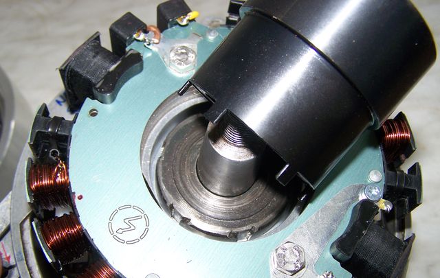
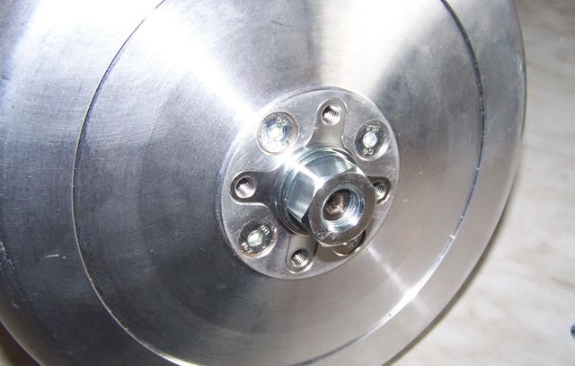 Rotor sicher verschrauben und dann die Schraubenabdeckung aufsetzen und sichern. |
|
|
|
|
 |
Damit sind die Arbeiten am Motor abgeschlossen. Die Z¸ndkerze wieder einschrauben. |
|
|
|
|
Die beiden Z¸ndspulen werden wie folgt mit den Kabeln verbunden:
Stecken Sie die lose mitgelieferte 2er-Steckerh¸lse auf diesen Stecker und f¸hren Sie die losen Kabel von der Lichtmaschine (rot und gelb) mit den Kontaktfahnen hinten in den Stecker ein. Achten Sie darauf, daþ die Steckerfahnen in dem Steckergeh‰use einrasten. Dabei ist strikt auf die korrekte Position dieser Kabel im Stecker zu achten:
|
|
|
| WICHTIG: Das braune Massekabel welches vom Stator kommt muss sowohl mit den Massepunkten der beiden Z¸ndspulen, als auch dem Massepunkt des Reglers verbunden werden! | |
|
|
|
|
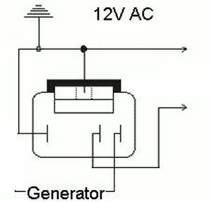
Das vom grauen Kabel der Statorspulen verl‰ngerte Lichtstromkabel
wird zum neuen Regler gef¸hrt und dort auf dessen ‰uþere, nahe an
der mittleren Klemme befindliche Steckverbindung geklemmt. ACHTUNG: nicht den anderen ‰uþere Kontakt nehmen! Dieser ist intern mit Masse (dem Aluhalteb¸gel) verbunden. Vom mittleren Kontakt geht dann die stabilisierte Wechselspannung zu den Verbrauchern. |
|
|
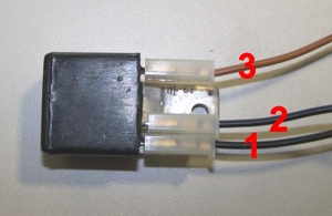 1 = Masse (auch intern verbunden mit dem Halteb¸gel) 2 = Ausgang der geregelten Spannung 3 = Eingang der ungeregelten Spannung |
|
Important safety and operating information for alternating current (AC) only systems |
| Practically, the DC regulator (rectifier/regulator) is the
better solution. It will take higher loads and is more versatile
in use.
The advantage of the AC regulator is in its smallness. This comes in handy in:
|
|
|
|
|
|
Important safety and operating information |
|
# |
Safety first! Please observe the general
health and safety regulations motor vehicle repair (MVR)
as well as the safety information and obligations indicated by the
manufacturer of your motorcycle. The timing marks on the material are for general guidance only during first installation. Please check after assembly by suitable means (stroboscope) that settings are correct to prevent damage to the engine or possibly even your health. You alone are responsible for the installation and the correctness of settings. |
|
# |
Ignition systems generate high tension! With our
material right up to 40,000 Volts! This may, if handled carelessly, not
only be painful, but outrightly dangerous.
Please do keep a safe distance to the electrode of your spark plug and
open high tension cables. Should you need to test spark firing, hold the
spark plug socket securely with some well insulating material and push
it firmly to solid ground of the engine block. Never pull sparkplug caps when engine is running. Wash your vehicle only with engine at standstill and ignition off. |
|
# |
Should you have received in the kit HT cables with a fixed rubber boot(which does not contain a resistor) you might have to use spark plugs with an inbuilt resistor (or replace the cap with one containing a resistor) to comply with your local laws. |
|
# |
After installation, please check tightness of all screws, even those preinstalled. If parts get loose during run, there will be inevitably damage to the material. We pre-assemble screws only loosely. |
|
# |
Give the newly installed system a chance to work, before you start
to check and test values, or what is worse apply changes to it. Our parts have been checked before delivery to you. You will not be able to check much anyway. At any rate do refrain from measuring the electronic components (such as ignition coil, regulator and advance unit). You risk severe damage to the inner electronics there. You will not get any tangible results from the operation anyway. Bear in mind that also your carburetor, your spark plugs and spark plug sockets (even if completely new) might be the reason for malfunction. The general experience with our systems is that the carburetor will have to be re-adjusted to lower settings. Should the system not start after assembly, first disconnect the blue (or blue/white) cut-off wire directly at the ignition coil (or in some cases advance unit) to eliminate any malfunction in the cut-off circuitry. Check ground connections carefully, make sure there is a good electrical connection between frame and engine block. In case of troubles, please consult our Knowledge Base first before you send off the material to us for checking |
|
# |
The spark of classic, points based ignition systems has with about 10,000 Volts comparatively little energy and looks therefore yellow and fat (which however makes it highly visible). The spark from our system is a high energy spark with up to 40,000 Volts and therefore is needle thin focused in form, and blue in colour, which makes it not so visible. Furthermore you get spark only at kick-start operated speeds and not by pushing the kick-lever down slowly with your hand (as you might get with battery based ignitions). |
|
# |
Systems using a twin outlet ignition coils have a few peculiarities. Please observe that during tests on one side, the other has either to be connected to an fitted spark plug or securely earthed/grounded. Otherwise there will be no spark on either side. Also with such open exits long and dangerous sparks may fly all over the coil. |
|
# |
Never do electric arc welding on the bike without completely disconnecting all parts containing semiconductors (ignition coil, regulator, advance) stator and rotor need not be taken off. The same is true for soldering. Before touching electronics disconnect the soldering iron from mains! Never use copper putty on spark plugs. |
|
# |
Electronics are very sensitive to wrong polarity. After work on the system, do check correct polarity of the battery and the regulator. Wrong polarity creates short circuits and will destroy the regulator, the ignition coil and the advance unit. As a rule, wiring will always be colour to colour. Instances, where colour jumps between wires are expressly mentioned in our instructions. |
|
# |
When you handle the new rotor, take care not to damage its magnets. Refrain from direct blows to the circumference of the rotor. When transporting never put the rotor over the stator. Observe our information relative to transport of the material. |
|
# |
Do not use spark plug sockets with a resistance of more than 5kOhm. Better use 1 or 2kOhm ones. Bear in mind that spark plug sockets do age and thereby increase their internal resistance. Should an engine start up only when cold, a defective spark plug socket and/or spark plug is very probably the cause. In case of problems check high tension cables too. Never use carbon fibre HT-cables, never use so called "hot wires" which promise to increase spark. |
|
# |
It is a good idea to cover the rotor in a thin layer of oil to reduce the risk of corrosion. |
|
# |
Never use a claw puller or a hammer to disengage the rotor. Its magnets might become loose in the event. We offer a special puller for disengaging the new rotor again (see assembly instruction)! |
|
# |
Should the motorcycle not be in use for some longer period, please disconnect the battery (so existing) to prevent current bleeding through the diodes of the regulator. Though, even a disconnected battery will empty itself after a while. |
|
# |
Please do observe these remarks, but at the same
time, don't be afraid of the installation process. Remember, that before you, thousands of
other customers have successfully installed the system. Enjoy driving your bike with its new electric heart! |
|
|