Powerdynamo bringt Ihrem Oldtimer Motorrad
wieder Zündung und
Licht
![]()
![]()
|
|
Powerdynamo bringt Ihrem Oldtimer Motorrad |
|
|||
|
|
|||||
| Assembly instructions for System 76 96 999 00 |
Version 28.07.2012 |
|---|
|
|
Designated use This system is designated to replace stock dynamo/alternator & ignition systems in vintage and classic motorcycles whose engine characteristics have not been modified aftermarket. This system is not a tuning system and it will not bring significant increases in engine output. It does however significantly enhance roadworthiness and comfort by offering better lighting, better function of side indicators and horn and, compared with the aging stock systems, increased reliability. As our system does not tamper with engine characteristics it does not increase emission of gaseous pollutants and noise. In most cases emission of pollutants should even be reduced due to better combustion. If used as designated the system therefore will not normally infringe the existing legal status of the motorcycle (this statement is valid for Germany, for other countries, please check locally against your road licensing regulations). This system is not suitable for use in competition events. If used other than the designated way, warranty will be voided and it might well be that you do not obtain the desired results or, worst you loose legal roadworthiness. |
| Please read these
instructions fully and carefully before starting work on your motorcycle Please bear in mind that any modification of the material as well as own repair attempts which have not been agreed with Powerdynamo may result in a loss of warranty. Also, please take note of the information provided on the information page for this system. Check that what you have bought really corresponds to the motorcycle you have. Wrong ignition settings may damage your engine and even hurt you during kickstart (violent kickbacks). Be careful during the first test runs. If needed change settings to safer values (less advance). During assembly check carefully that the rotor (flywheel) does not touch the stator coils or anything else, which may happen due to various circumstances and lead to severe damage. |
|
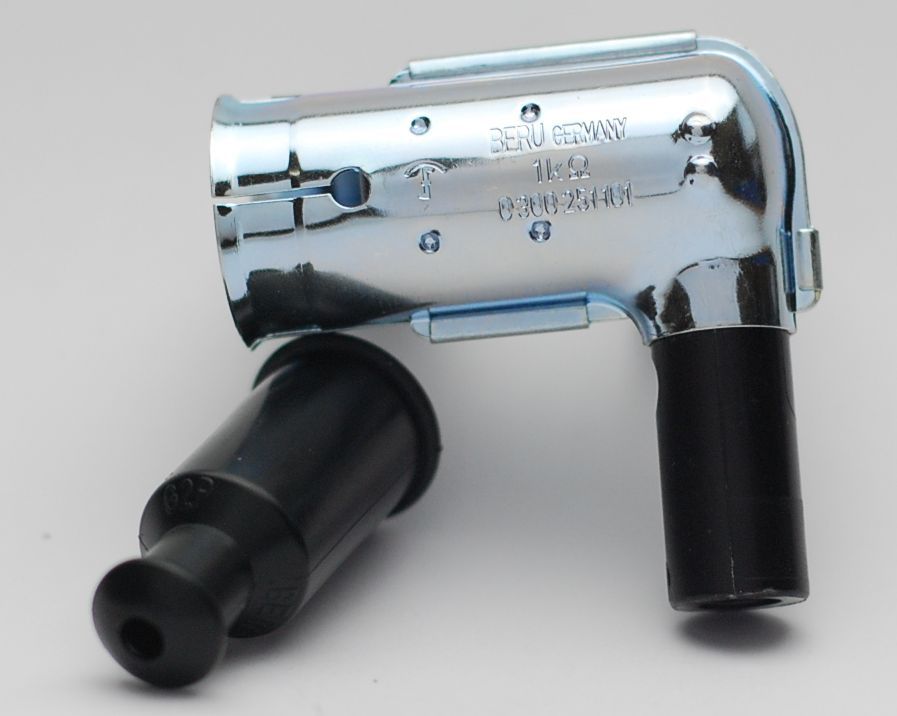
| Please always use shielded spark plug caps (but not more than 5Kohm) with this system as the hall trigger element is very sensible and may catch the emission of a spark which can lead to ignition disturbances, even failure. | |
| Our systems are NOT tested for use with third party electronic devices and may cause damage to such parts. Possibly existing electronic tachometers will not work with the new system. Read our information for suitable solutions. Possibly existing safety switches and electronic valve controls are not supported. It might be that your motorcycle was originally equipped with an ignition that did limit top speed for legal reasons. The new system does not have such a facility, so check your legal situation beforehand. | |
| If you have no expertise for the installation have it done by an expert or at a specialist's workshop. Improper installation may damage the new system and your motorcycle, possibly even lead to bodily harm. | |
| Before you order a system, please check whether a puller
tool for the new rotor is included in the kit. If not,
better order it at the same time. You might want to order light bulbs,
fuse, horn,
flasher
unit etc. Never use anything other than the recommended puller tool to pull the new rotor again. Damage to the rotor as a result of use of other tools or methods is not covered by warranty. |
|
| The rotor is sensible to blows (including during transport). Before assembly, please always check for damage (on rotor without magnet plastification try to push the magnets aside with your fingers). After impact the glued in magnets might have broken loose, sticking to the rotor solely by magnetic force, so that one does not notice right away. During engine run the damage would be considerable. Before placing the rotor onto the engine, please make sure that its magnets have not collected any metal objects such as small screws, nuts and washers. That equally would lead to severe damage. | |
|
|
If you have access to the Internet, best view those instructions online. You get larger and better pictures by clicking onto them and possibly updated information. System list at http://www.powerdynamo.biz |
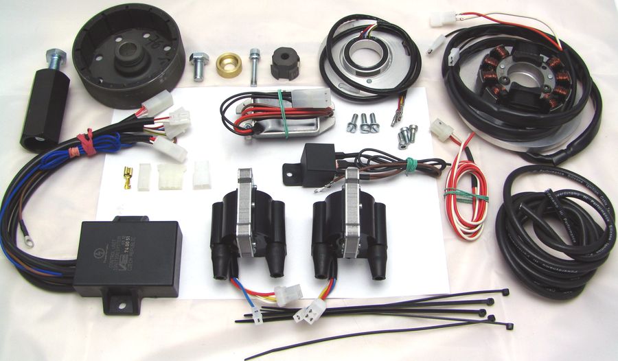 |
You should have received those parts:
|
|
|
|
| Make sure your Honda rests securely, preferably on an
elevated work bench and that you have good access to the engine. You do yourself a favour when you first completely read the instructions before you start work. Disconnect your battery and take it out of the motorcycle for the time
of work. |
|
|
|
|
|
Short overview of work to be done: |
|
|
|
|
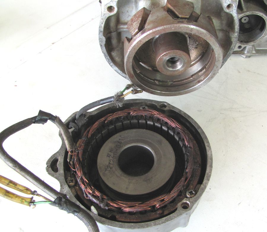 |
Remove the stock alternator and regulator |
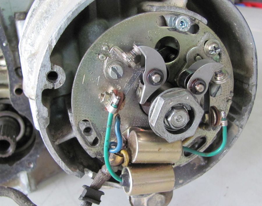 |
Remove the stock ignition setup (points) as well as the ignition coils. |
|
|
|
| installing alternator: | |
|
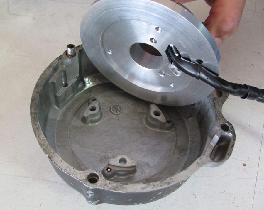
Place the new rotor (flywheel) onto the crankshaft. Check carefully that it does not interfere somewhere and that it sits well on the taper. Position in respect to crank position is irrelevant. The small part of the shaft protruding from the rotor hub will be covered by the spacer bit and the rotor will be tighted with the new M10x1 bolt. |
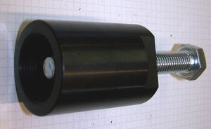 |
To pull the new rotor, use only the provided puller M27x1,25 (order-no.: 72 98 799 99). Note: Never use a claw puller, a hammer or any other device, that will shake the magnets off. |
|
|
|
 |
Now place the new stator plate with the coil on it into the magneto cover. NOte that it centers with its bottom in the 3 elevations on the cover. Make sure the plate really sits there correctly and not loopsided. |
|
|
|
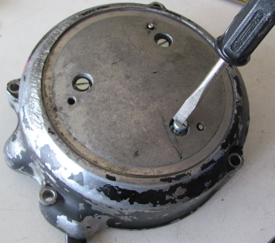 |
Screw the plate to the cover with the 3 screws M5x15 and the washers provided. |
|
|
|
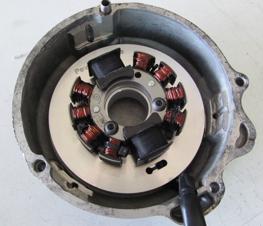 |
THis is the ready magneto cover. |
|
|
|
| Installation of hall element: | |
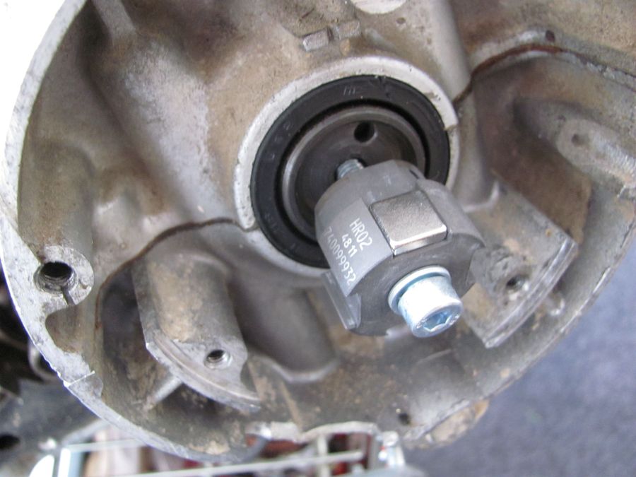 |
Place the hall rotor with its smaller diameter side directly onto the flat edge of the crank (where the centrifugal govenor was) and fasten it there loosely by the provided screw M6x35, the washer and the springwasher.
|
|
|
|
 |
Now place the hall plate over the new hall rotor into the recess where the points plate had been. Put the screws into the middle of the oblong holes to get room for adjustment. Note: The position of the plate is only important in terms of the direction of the wire exit, which should be straight and neat. Fasten the 3 screws M5, not forgetting the washers. The hallsensor element and the adapter it sits in are delivered pre-assembled and should remain that way. No need to take it apart.
|
 |
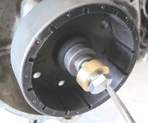
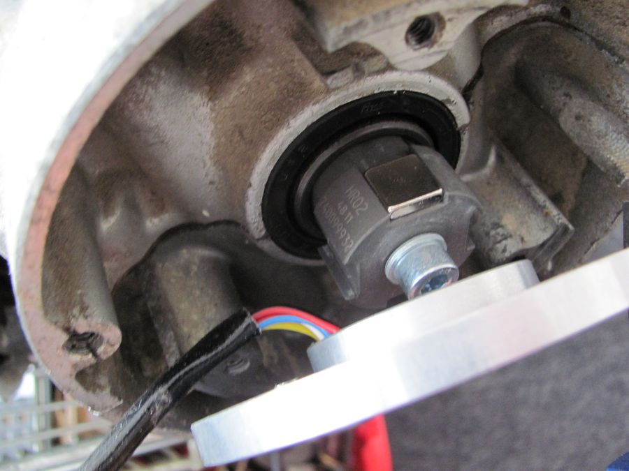
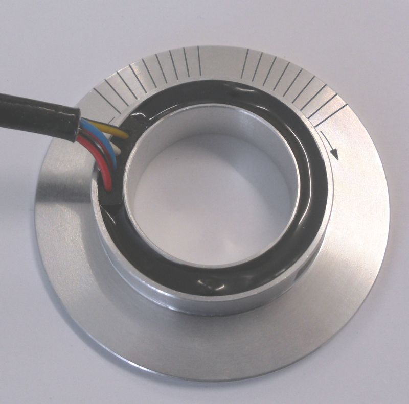
The hall rotor sits correctly in height when it is fully submerged inside the hall element as shown in the picture here. Now time ignition as per instructions you find below. Once you have done this, fasten the screw M6 to fix the hall rotor to the crank. Make sure the crank does not move in the process. |
|
|
|
|
You may see the graphic illustration of the following information in wire diagram 7451-4 |
|
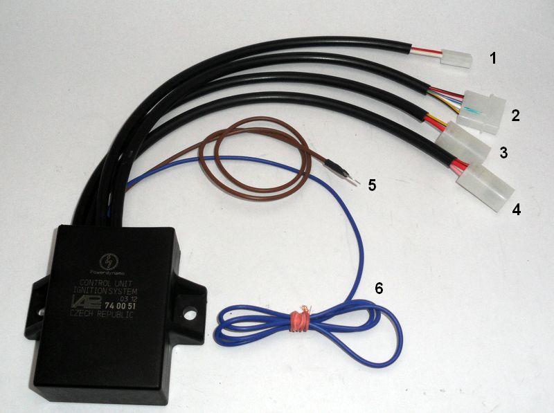
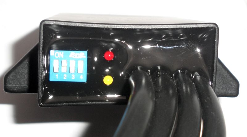
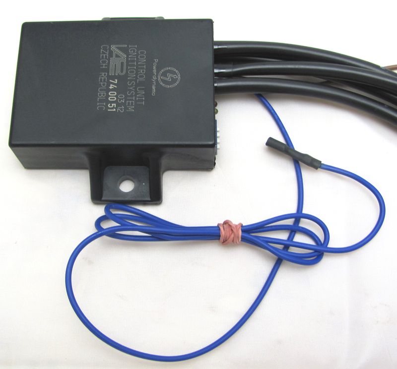
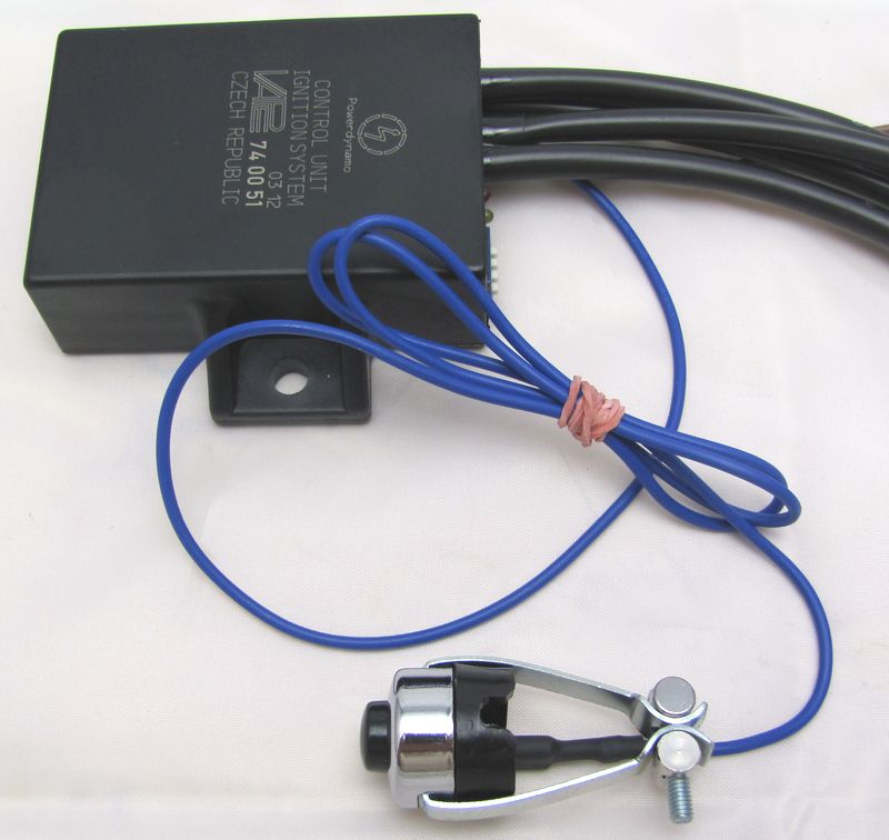
| Start with familiarising with the wires and plugs at the advance unit (a box labeled 74 00 51). | |
|
You have got there:
|
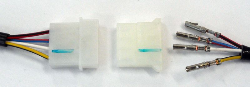
| Start with connecting the wire from the hall sensor unit to the advance. | |
|
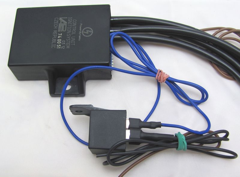
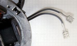
After You have led the wire from the hall unit though possible tight openings you put the plastic plug cover on the terminals at the wire. Make sure that the wire colours match 1:1 from hall wire to advance. Both plug parts have small elevations to give you some orientation which side to connect together. In the picture we have highlightend those elevations in green. Please double check that you have all wire colours one to one (same colour to same colour). |
|
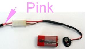
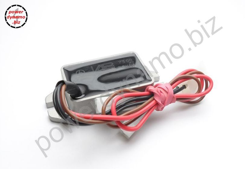
Identify the wire bundle at the advance which contains the pink wire. (Pos. 4
in above overview picture). You also got a (setup) cable with wires
red and white, the plug of which matches the plug at advance containing the pink.
Here you now connect the plugs and get
To set timing you first need to connect a battery ( 6, 9 or 12V) to the setup cable. Red to plus and white to minus, do not confuse this! |
|
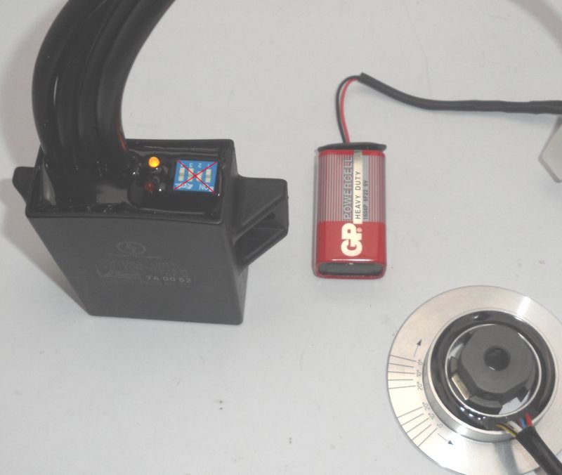
Sure that the hall unit shown here as a free part is at this point already
fixed to the engine.
When you turn the still loosely on the shaft sitting hallrotor
and have the battery connected you will notice that one of the diodes
starts to shine, turning further stops to shine until some 180 degrees
further the second diode does the same. |
|
|
|
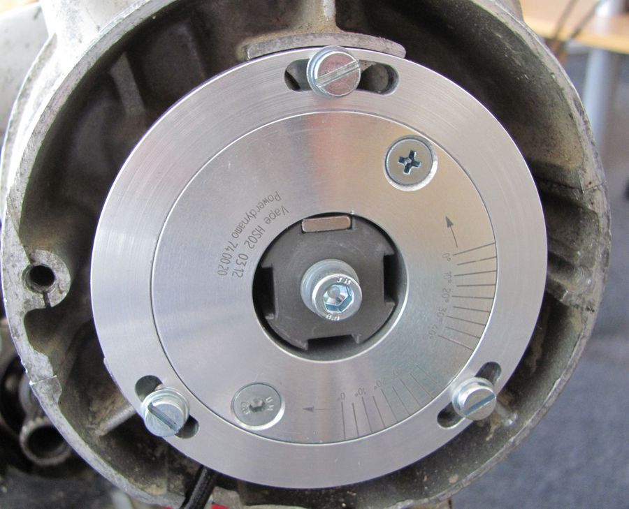
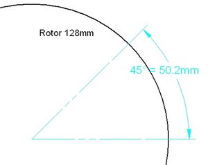
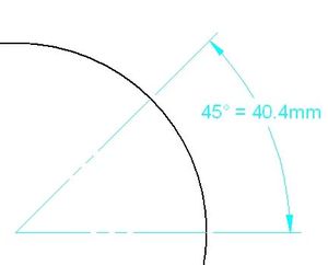
| Now you need to do some basic crank setting. For this you have to bring the crank in a position where the piston of the cylinder which fires first is 45 degrees before TDC. Those 45 degrees have nothing to do with the real advance of the system, they are some constant the system needs to find its way. | |
|
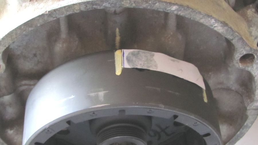
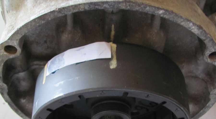
You may set the 45 degrees using the new rotor of
the Powerdynamo alternator as follows:
Now
turn the rotor anticlockwise till the second marking has reached the
position the first marking had been in - and you have set the crank into
45°! BTDC. |
|
|
|
|
|
|
|
With crankshaft in this position (45 degrees before TDC of first firing cylinder) and setup wire connected you turn the (loosely fitted) hall rotor into driving direction of the shaft - clockwise - until the yellow diode starts shining. Than slow your turning until the yellow diode stops shining. In this position (moment it stops shining) carefully fasten the hall rotor without changing its position relative to the crank. Timing is now set. The rest is done by the advance unit. |
|
Setting the different characteristics needed by a system (advance in relation to crank revs) is done by the advance unit. IT contains different curves. The needed one is selected by setting the n4 small switches as indicated in the instructions. |
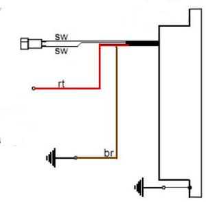
| Take the setup cable off again. Connect the 2 twin ignition coils (wires 3 and 4), the cable (nr 1) to the alternator, the brown to goud ground and the blue to the cut off device. | |
| Ignition is now timed and ignition wiring set up. | |
|
|
|
|
To stop engine run, the blue wire from the
advance unit has to be connected to ground. As long as it has ground, you can not start the engine. In case of ignition trouble always first disconnect this blue wire to exclude some error in the switch off circuit (happens quite often!). DO not disconnect the wire with engine running. It carries voltage which could hurt you. Please note that to use the relay, you need a working battery. Otherwise the relay can not operate and your engine can not be started! |
|
|
|
|
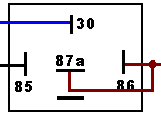
The best way to connect the blue kill wire to ground is to use the supplied switch off relay (please note that it is not any, but a special relay) The brown wire from pins 86 and 87a connect to ground. The black from pin 85 connects to a terminal at the main switch which carries voltage when switch is in ON position. Pin 30 of the relay takes the blue kill wire from the advance
|
|
|
|
|
If you want to drive without battery you have to use some other means to connect the blue wire to ground for switch off (that is to connect at least as long as it takes till engine stand still) The obvious way is to use a kill switch. Some motorcycles might already
have an emergency cut off which might do the same (check whether it
connects against ground). Note that your handlebar should have good
ground. Otherwise engine will not cut off, but you may feel the voltage as
you than are ground!
|
|
|
|
|
|
|||||||||||||||||||||||||||||||||||||||||||||||||
| Now set the needed advance curve with the 4 small switches at the advance unit: | |||||||||||||||||||||||||||||||||||||||||||||||||
|
With this recommended switch position the system starts at 8° BTDC and advances to 26.5° BTDC at 2500 revs/min. | ||||||||||||||||||||||||||||||||||||||||||||||||
|
|||||||||||||||||||||||||||||||||||||||||||||||||
|
|
|||||||||||||||||||||||||||||||||||||||||||||||||