Powerdynamo brings new ignition & light
to your vintage motorcycle
![]()
![]()
|
|
Powerdynamo brings new ignition & light |
|
|||
|
|
|||||
|---|---|---|---|---|---|
| Assembly instructions System 71 13 499 00 |
Version 18.02.2017 |
|
If you can install your stock dynamo/alternator and
possess basic mechanical skills, you can install a Powerdynamo! |
|
| Powerdynamo can not monitor the compliance to those instructions, nor the conditions and methods of installation, operation, usage and maintenance of the system. Improper installation may result in damage to property and possibly even bodily injury. Therefore we assume no responsibility for loss, damage or cost which result from, or are in any way related to, incorrect installation, improper operation, or incorrect use and maintenance. We reserve the right to make changes to the product, technical data or assembly and operating instructions without prior notice. | |
|
|
Please read these
instructions fully and carefully before starting work on your motorcycle Please bear in mind that any modification of the material as well as own repair attempts which have not been agreed with Powerdynamo may result in a loss of warranty. Do not cut off wires. This leads to a loss of reverse polarity protection and often results in damage to electronics. Also, please take note of the information provided on the information page for this system. Check that what you have bought really corresponds to the motorcycle you have. During assembly check carefully that the rotor (flywheel) does not touch the stator coils or anything else, which may happen due to various circumstances and lead to severe damage. |
| Designated use This system is designated to replace stock dynamo/alternator in vintage and classic motorcycles. As it is a voltage generating unit only, it will in not change your engine characteristics. In most cases it will supply more electric power and hence enhance roadworthiness and comfort by offering better lighting, better function of side indicators and horn and, compared with the aging stock systems, increased reliability.
The system does not replace your ignition. Ignition must be either a compleately selfsupplying magneto
or there has to be a battery in the system. The system has not been tested to work with a third party
electonic ignition. it may work with it, but also may not and even may damage it.
At any rate the system will charge your battery well.
This is a replacement system and not a copy of the stock material. The parts in this system therefore look different and might fit differently (notably ignition coil and regulator) requiring some adaptation by you. |
|
| During assembly imperatively start with assy of engine based parts to see that those really fit before you start fitting the external parts. In many cases customers assemble those first and thereby often modify them in breach of warranty which renders them unfit for renewed sale. Replacing old electrical systems is not a matter of taking something from a supermarket shelf as there have been very many types, versions and possibly unknown aftermarket modifications which harbour plenty of room for error. | |
| Our systems are NOT tested for use with third party electronic devices (such as GPS, mobile phones, LED lighting or electronic ignition)and may cause damage to such parts. Possibly existing electronic tachometers will not work with the new system. Read our information for suitable solutions. Possibly existing safety switches and electronic valve controls are not supported. | |
| If you have no expertise for the installation have it done by an expert or at a specialist's workshop. Improper installation may damage the new system and your motorcycle, possibly even lead to bodily harm. | |
| Before you order a system, please check whether a puller
tool for the new rotor is included in the kit. If not,
better order it at the same time. You might want to order light bulbs,
fuse, horn,
flasher
unit etc. Never use anything other than the recommended puller tool to pull the new rotor again. Damage to the rotor as a result of use of other tools or methods is not covered by warranty. |
|
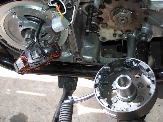
| The rotor is sensible to blows (including during transport). Before assembly, please always check for damage (on rotor without magnet plastification try to push the magnets aside with your fingers). After impact the glued in magnets might have broken loose, sticking to the rotor solely by magnetic force, so that one does not notice right away. During engine run the damage would be considerable. Before placing the rotor onto the engine, please make sure that its magnets have not collected any metal objects such as small screws, nuts and washers. That equally would lead to severe damage. | |
|
|
If you have access to the Internet, best view those instructions online. You get larger and better pictures by clicking onto them and possibly updated information. System list at http://www.powerdynamo.biz |
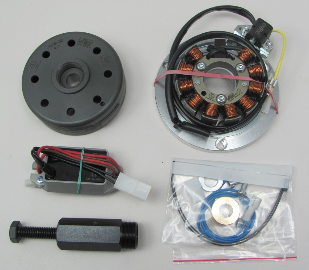 |
You should have received those parts:
|
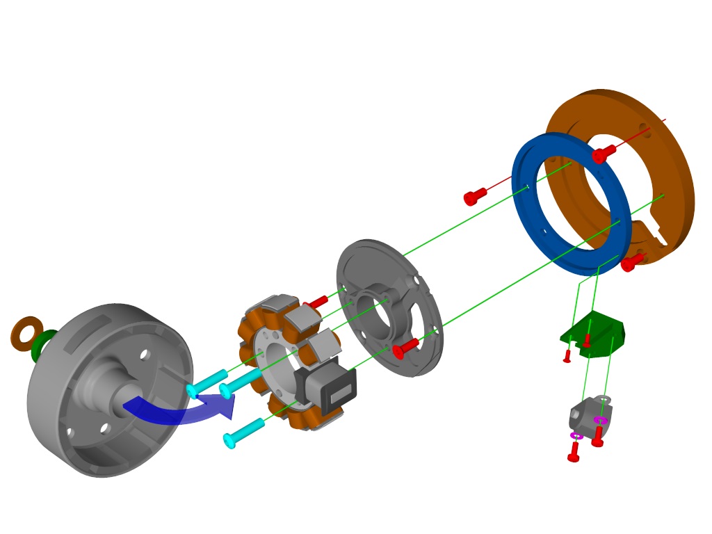 |
This is the overview of the engine mounted parts. The stator unit (adapter plates and coil) arrives in one piece and does not need to be taken apart. It is placed as one unit onto the engine (older versions consisted of different plates which had to be placed individually) |
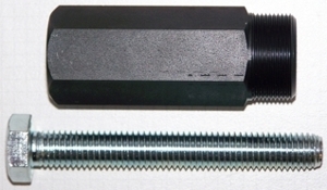 |
To disengage your new rotor again, only use the supplied long puller M27x1,25 (part-no.: 71 69 999 99). Note: Never use a claw puller, a hammer or any other device, that will shake the magnets off. |
|
|
|
| Make sure your motorcycle rests securely,
preferably on an elevated work bench and that you have good access to the
dynamo side of the engine.
Disconnect your battery and take it out of the motorcycle. Note that you will install a 12 volts system, so you will either need a 12 volt battery or you use the option of driving without. You will still have to replace all light bulbs to 12 volt ones. The horn may stay at 6 volts. For driving without battery, please observe our information on driving without battery. |
|
|
|
|
 |
Disconnect all wires to the old magneto, points. regulator, rectifier, CDI and ignition coils and take those parts off. |
|
|
|
|
Take the woodruff key from the crank pin. It will not be needed anymore and prevent assembly. If you forget this right at start, you will have to take the whole new unit off again to get access to the key. No worry over this lost woodruff. Details see (online) here |
|
|
|
|
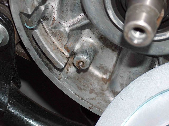 |
Check whether there is still a small dowel at the circumference of the dynamo seat. This is part of the old alternator arrangement preventing the customer from installing the original unit wrong side up. If the dowel is still there, it has to be removed (it can be pulled with a pair of pliers). If the pin is left untreated, the new plate will not be sitting level to engine and that will cause the new rotor to touch the coils, leading to total destruction of the material. |
|
|
|
 |
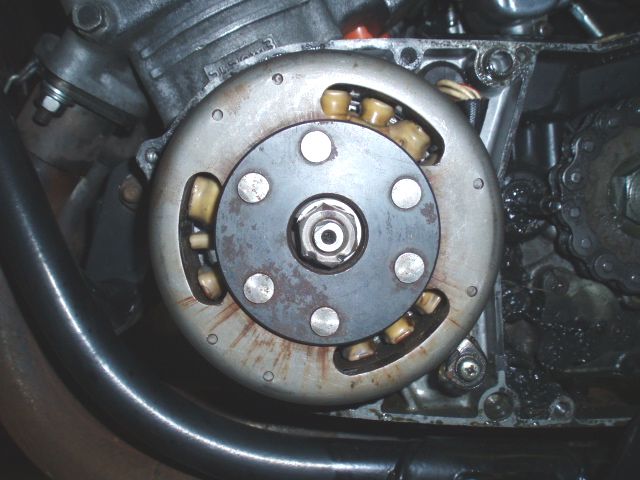
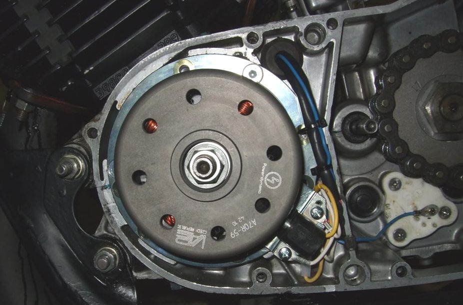
Place the stator unit onto the engine. Pickup module showing to about 5 o�clock (picture shows older version, in new one there are no unused screw holes) |
|
|
|
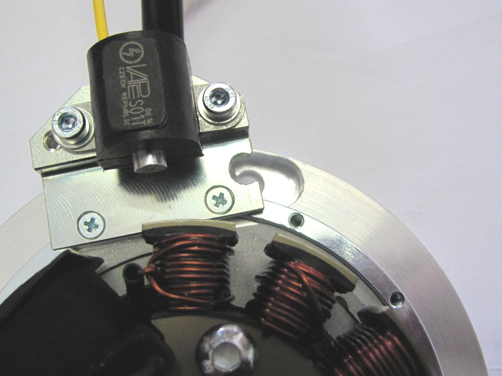 |
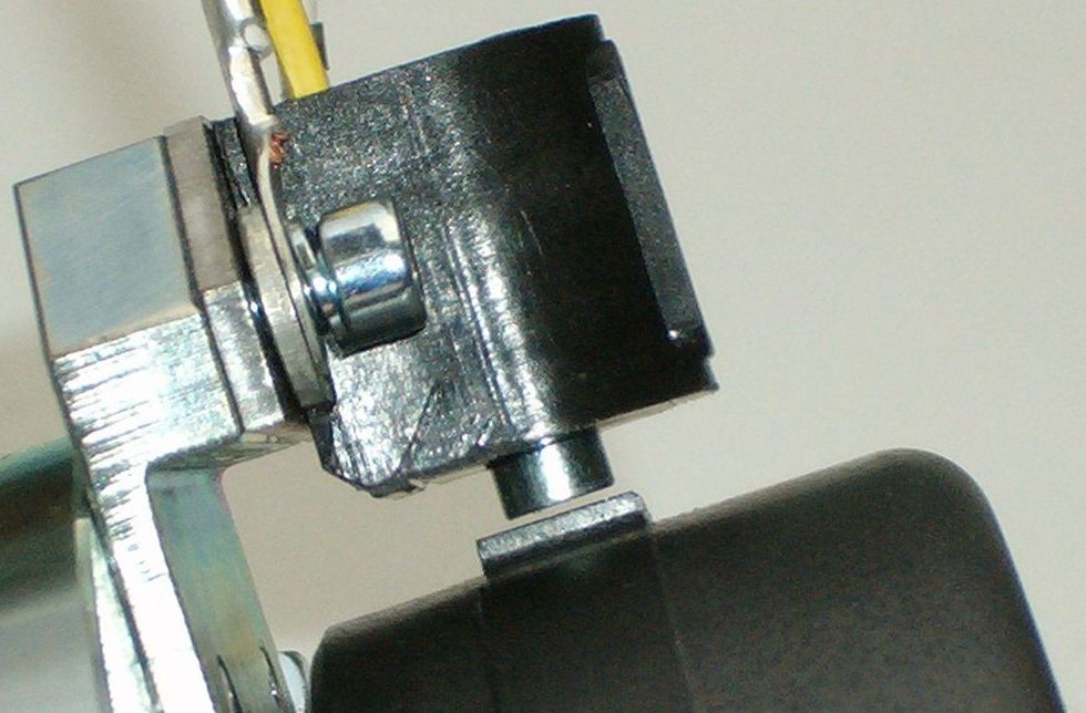
The stator assembly is fastened by 3 supplied socket head screws M6x12. As the one of them near the pickup is obscured by the pickup holder, the holder has been opened a little so that the allan key can be applied. There is no need to take the sensor (pickup) holder off. |
|
|
|
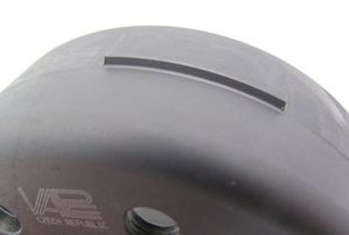 |
Have a look at the new rotor. You will find on its circumference 2 straight protrusions (noses). They serve for impulse with the option to take passing time for calculating engine speed. |
|
|
|
 |
|
|
|
|
 |
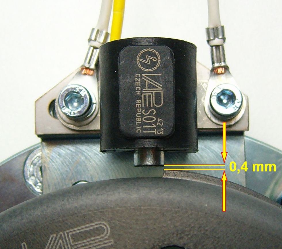
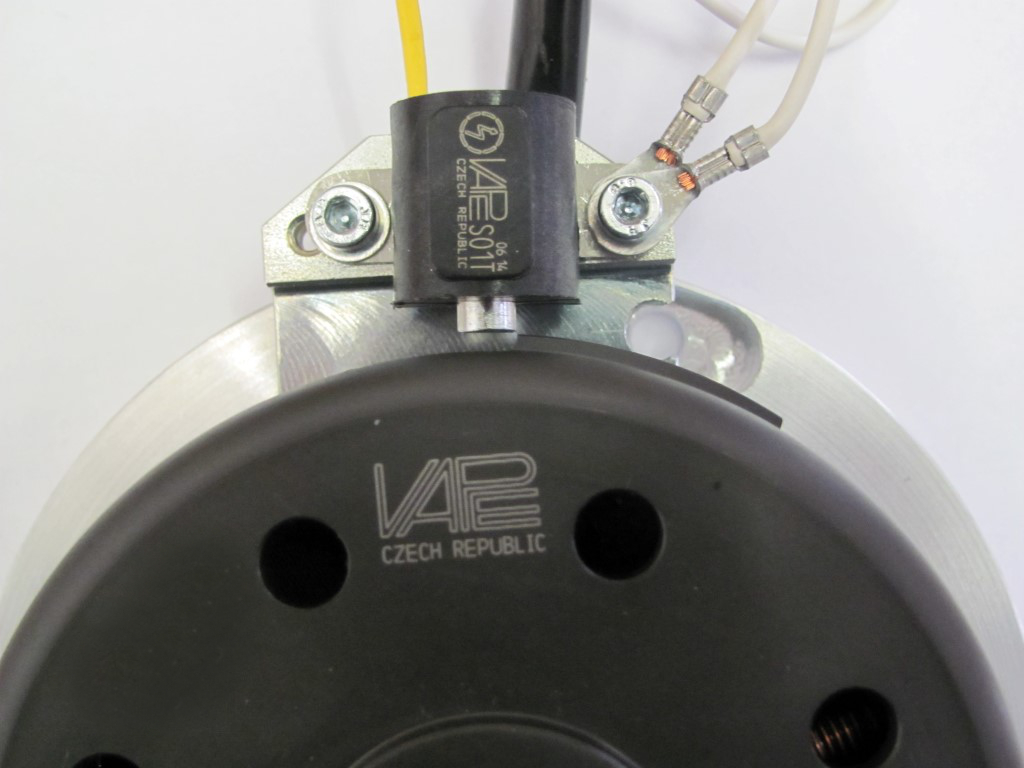
Check that the metal pin of the sensor runs about middle of the trigger sign on the rotor. The more it is outside, the harder starting is.
|
|
|
|
|
|
|
|
|
 |
Tighten the rotor with the stock nut, not forgetting the supplied washer and bush as the threading is quite long. To undo the rotor use a puller M27x1,25. With that the work on the engine is finished. Put the spark plugs back. |
|
|
|
|
|
|
|
Connect the parts as shown in wiring diagram pickup_gonly_102 |
||
|
* |
To facilitate wire exit through the often small openings in the engine casing, the plastic plug of the generator's wiring that leads to the ignition coil has not been put onto the wire terminal. You should place the plug there only once all has been properly installed on the engine side. | |
|
* |
|
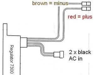
The new regulator/rectifier has 4 wires
|
| The two black cables leading from the generator ... |
... should be first introduced into the supplied twin plastic plug housing. This housing connects to the plastic plug at the end of the 2 black wires on the regulator. It does not matter which black is at which side, as there is AC. |
|
| The brown cable from the regulator ... |
... should connect to either battery minus or good ground if there is no battery. |
|
|
The red cable from the regulator ... Take care: |
... should connect to either battery 12V PLUS or if there is no battery to the wiring that runs to your consumers (normally main switch intake pin). |
|
| If you use a battery, make sure that you have a 15A-fuse between battery and vehicle circuitry. | ||
| * |
Remains the yellow wire at the sensor |
Here you connect your Pickup impuls to the 3rd party material as per
instructions supplied with those materials. Never introduce any voltage into this yellow cable! It would destroy the sensor |
|
* |
Finally - and before installing the battery and before the first kickstart - please re-check carefully all connections and fitments against the wiring diagram. Do check battery and light bulbs for correct voltage (12V). Should something not work, please consult our trouble-shooting guide on our homepage. As a first step disconnect the blue wire from the coil and re-test. |
|
| * |
IMPORTANT: During crank shaft repair the dynamo shaft is often
machined and gets shorter. The result is a rotor sitting lower, possibly
touching now with its rivets the stator coil. The result is a destroyed
stator and ignition failure. For more detail and how to check see (online) here. |
|
|
|
Important safety and operating information for dynamo only systems |
|
# |
Safety first! Please observe the general health and safety regulations motor vehicle repair (MVR) as well as the safety information and obligations indicated by the manufacturer of your motorcycle. |
|
# |
After installation, please check tightness of all screws. If parts get loose during run, there will be inevitably damage to the material. We pre-assemble screws only loosely. |
|
# |
Give the newly installed dynamo a chance to work, before you start
to check and test. Our parts have been checked before delivery to you. You will not be able to check much anyway. At any rate do refrain from measuring the electronic regulator other than the output voltage. You risk several damages to the inner electronic there. You will not get any tangible results from the operation anyway. Check ground connections carefully and, to be on the safe side and for testing, put an additional ground wire from the regulator directly to the engine block. |
|
# |
Never do electric arc welding on the bike without completely disconnecting all parts containing semiconductors (ignition coil, regulator, advance) stator and rotor need not be taken off. |
|
# |
Electronics are very sensitive to wrong polarity. After work on the system, do check correct polarity of the battery and the regulator. Wrong polarity creates short circuits and will destroy the regulator which is for negative earth only. |
|
# |
When you handle the new rotor, take care not to damage its magnets. Refrain from direct blows to the circumference of the rotor. When transporting never put the rotor over the stator. Observe our information relative to transport of the material. |
|
# |
It is a good idea to cover the rotor in a thin layer of oil to reduce the risk of corrosion. |
|
# |
Never use a claw puller or a hammer to disengage the rotor. Its magnets might become loose in the event. We offer a special puller screw for disengaging the new rotor again (see assembly instruction)! |
|
# |
Should the motorcycle not be in use for some longer period, please disconnect the battery (so existing) to prevent current bleeding through the diodes of the regulator. Though, even a disconnected battery will empty itself after a while. |
|
# |
Please do observe those remarks, but at the same
time, don't be afraid of the installation process. Remember, that before you, thousands of
other customers have successfully installed the system. Enjoy driving your bike with its new electric heart! |
|
|