Powerdynamo brings new ignition & light
to your vintage motorcycle
![]()
![]()
|
|
Powerdynamo brings new ignition & light |
|
|
|
||
|---|---|---|
| Assembly instructions for System 70 91 499 12 |
Version 16.07.2008 |
|
If you can install your stock dynamo/alternator and
possess basic mechanical skills, you can install a Powerdynamo! |
|
| Powerdynamo can not monitor the compliance to those instructions, nor the conditions and methods of installation, operation, usage and maintenance of the system. Improper installation may result in damage to property and possibly even bodily injury. Therefore we assume no responsibility for loss, damage or cost which result from, or are in any way related to, incorrect installation, improper operation, or incorrect use and maintenance. We reserve the right to make changes to the product, technical data or assembly and operating instructions without prior notice. | |
|
|
Please read these
instructions fully and carefully before starting work on your motorcycle Please bear in mind that any modification of the material as well as own repair attempts which have not been agreed with Powerdynamo may result in a loss of warranty. Do not cut off wires. This leads to a loss of reverse polarity protection and often results in damage to electronics. Also, please take note of the information provided on the information page for this system. Check that what you have bought really corresponds to the motorcycle you have. During assembly check carefully that the rotor (flywheel) does not touch the stator coils or anything else, which may happen due to various circumstances and lead to severe damage. |
| Designated use This system is designated to replace stock dynamo/alternator in vintage and classic motorcycles. As it is a voltage generating unit only, it will in not change your engine characteristics. In most cases it will supply more electric power and hence enhance roadworthiness and comfort by offering better lighting, better function of side indicators and horn and, compared with the aging stock systems, increased reliability.
The system does not replace your ignition. Ignition must be either a compleately selfsupplying magneto
or there has to be a battery in the system. The system has not been tested to work with a third party
electonic ignition. it may work with it, but also may not and even may damage it.
At any rate the system will charge your battery well.
This is a replacement system and not a copy of the stock material. The parts in this system therefore look different and might fit differently (notably ignition coil and regulator) requiring some adaptation by you. |
|
| During assembly imperatively start with assy of engine based parts to see that those really fit before you start fitting the external parts. In many cases customers assemble those first and thereby often modify them in breach of warranty which renders them unfit for renewed sale. Replacing old electrical systems is not a matter of taking something from a supermarket shelf as there have been very many types, versions and possibly unknown aftermarket modifications which harbour plenty of room for error. | |
| Our systems are NOT tested for use with third party electronic devices (such as GPS, mobile phones, LED lighting or electronic ignition)and may cause damage to such parts. Possibly existing electronic tachometers will not work with the new system. Read our information for suitable solutions. Possibly existing safety switches and electronic valve controls are not supported. | |
| If you have no expertise for the installation have it done by an expert or at a specialist's workshop. Improper installation may damage the new system and your motorcycle, possibly even lead to bodily harm. | |
| Before you order a system, please check whether a puller
tool for the new rotor is included in the kit. If not,
better order it at the same time. You might want to order light bulbs,
fuse, horn,
flasher
unit etc. Never use anything other than the recommended puller tool to pull the new rotor again. Damage to the rotor as a result of use of other tools or methods is not covered by warranty. |
|
| The rotor is sensible to blows (including during transport). Before assembly, please always check for damage (on rotor without magnet plastification try to push the magnets aside with your fingers). After impact the glued in magnets might have broken loose, sticking to the rotor solely by magnetic force, so that one does not notice right away. During engine run the damage would be considerable. Before placing the rotor onto the engine, please make sure that its magnets have not collected any metal objects such as small screws, nuts and washers. That equally would lead to severe damage. | |
|
|
If you have access to the Internet, best view those instructions online. You get larger and better pictures by clicking onto them and possibly updated information. System list at http://www.powerdynamo.biz |
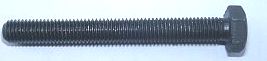 |
To pull the old rotor, you will need a puller tool M10x90 (Teil Nr. 89 99 026). |
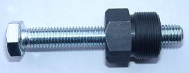 |
To pull the new rotor again, you will need a puller tool M27x1,25 (part
99 99 799 00 -not provided-).
Note: Never use a claw puller, a hammer or any other device, that will shake the magnets off. |
|
|
|
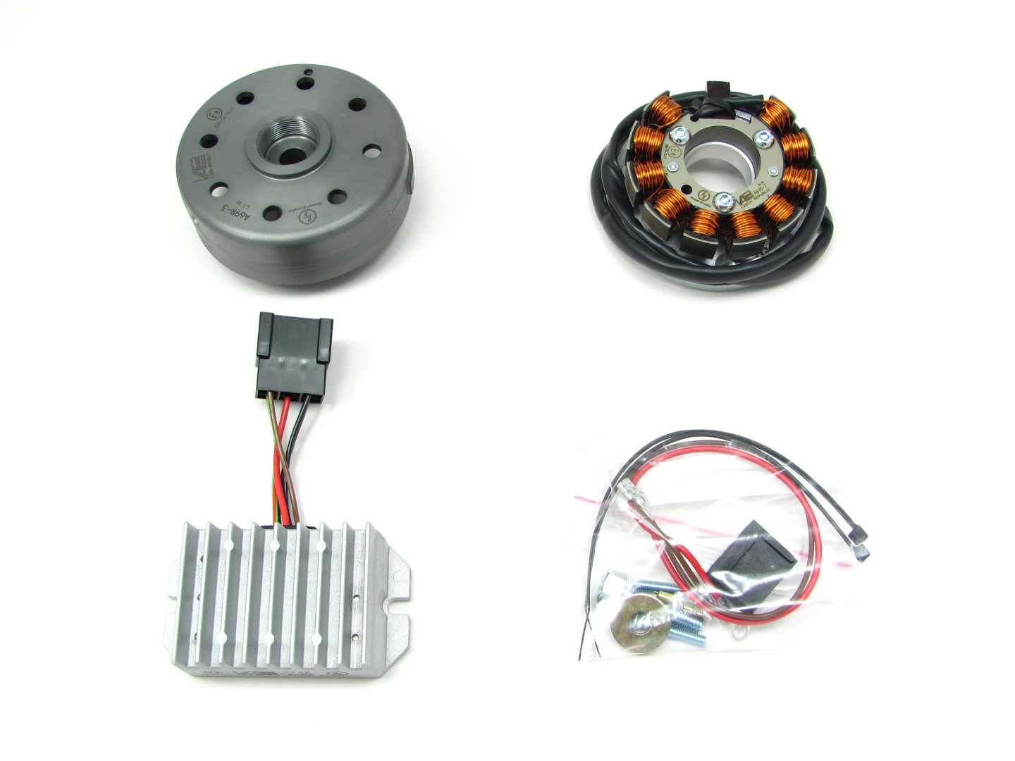 |
You should have received those parts! Please pay attention: |
|
|
|
| Make sure your
bike rests securely on her stand, preferably on an elevated work
bench and that you have good access to the generator side of the engine.
Disconnect your battery and take it out of the motorcycle. Note that should you be installing a 12 volt system, you will either need a 12 volt battery or you use the option of driving without. You will still have to replace all lightbulbs to 12 volt ones however in that case too. The horn may stay at 6 volts. For driving without battery, please observe our information on driving without battery. Technical it is possible to drive your bike without the battery. But consult your local road traffic regulators. |
|
|
|
|
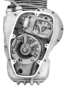 |
At first replace the old parts.
Loose the 5 hex screws of the generator cover and take it off. Disconnect the cables from your old generator and remove it. Pull off the old rotor with the puller tool (pay attention: the holding screw has a couter-clockwise tap, so you have to screw clockwise for pull off). |
|
|
|
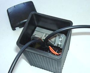
| Should have your
AWO a regulator in the battery case, remove it. Remove too the cable from
the centre pin of the regulator (F) to the fuse case and cut-off both
other cables (51/61) so short as possible. These are death wires. If you
be able and willing to pull those cables out of the harness to the motor,
do it.
ATTENTION: Do not remove any other cables from the AWO, especially not this from the battery positive pole to the ignition lock. You will need it further on. |
|
|
|
|
|
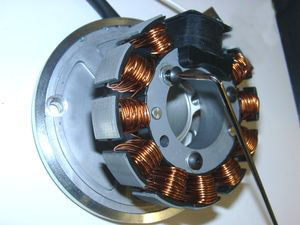
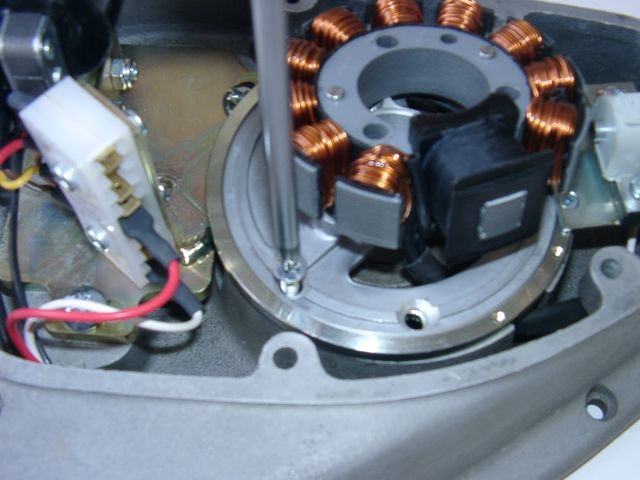
The new stator unit
is pre-assembled, so that its construction is easier to recognise. For the
mounting it has to be partly disassembled.
Pay attention: do not damage the paint insulation of the coils. Loose the 3 hex screws they hold the stator on the ground plate. Pull the stator in that way from the plate, so you can handle the 2 mounting holes below. |
|
|
|
|
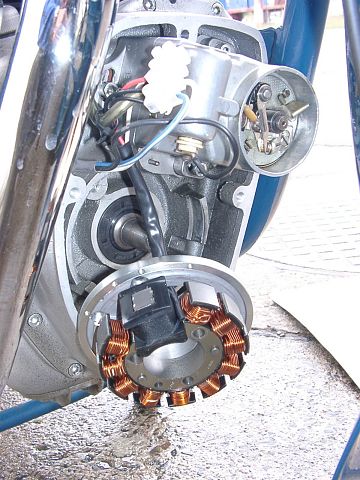
Put the pre-assembled stator plate (steel ring, aluminium plate and sensor) instead of the generator in the crank case. The sensor shows to the ground and the cable shows left up to the terminal of the ignition coil plate (if you look from the front on the unit). Screw down the ground plate (steel ring and inner aluminium plate) on the crank case with the 2 countersunk screws M6x30. The ignition coil unit hang loose on the cables further on. Now you have to replace the stator on the ground plate. Take care, that no cable is pinched. The coil has to be fitting good on the ground plate - nearly "hearable engage". If is it ain't so, and the coil fits "soft" on the ground plate, is a cable in the way and there is a risk of damaging by contact of the rotor. Screw down the stator with the 3 hex srews M6x30. |
|
|
|
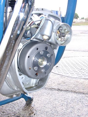 |
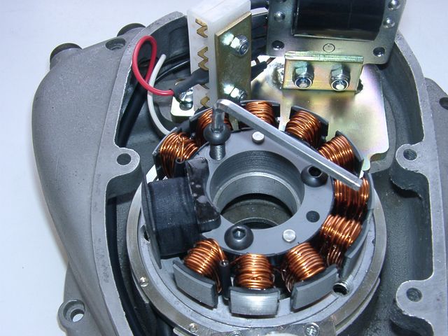
Place the rotor loosely onto the crank and check
that it may move freely above the statorbase. Fasten the rotor carefully with
the screw M7x40 (counter-clockwise tap). Please don't
forget to use the washer.
To pull the new rotor again, you will need a puller tool M27x1,25. |
|
|
|
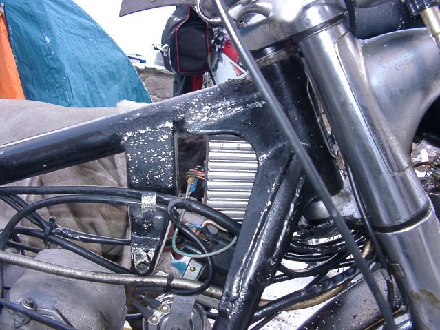
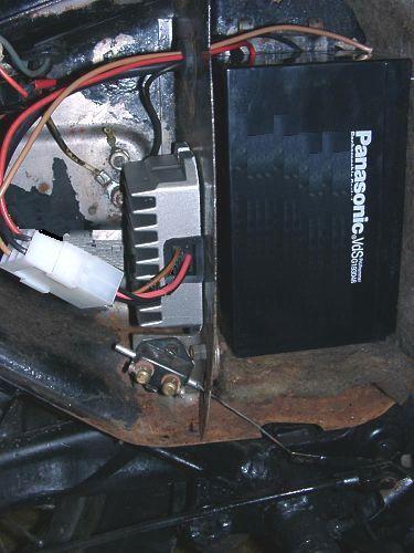
| Now you have to installate the extern parts (rectifier/regulator and the controller). You can place it beneath the tank in the frame triangle or on the sport-version in the side case. For the AWO-Tour, in case of lack of space, we have make the cables any longer. So you can hide the parts in an empty battery case (see our offer). If you like to use this option, you have to saw off one of the both stays. This is not a breach of warranty, as far as you don't saw into the case and you really only cut off the stay. | |
|
|
|
|
|
| Now you have to lay the harness on the frame. At first lead the harness upwards the frame beneath the tank and then to the mounting place of the new regulator. |
|
|
Connect the parts as shown in wiring diagram g-only: |
||
|
* |
|
The new regulator/rectifier has a compact plug with 6 positions, of which one is not used. A female plug cover fitting to this plug is delivered. Into this female plug you have to insert the following wires (which have terminals that snap into the plug): |
| The two black cables leading from the generator ... |
... connect to pins 1/4 of the new regulator (from there equally black wires lead inside the unit). It does not matter which wire connects to which of the both terminals (1/4) as they carry alternating current. |
|
| The new brown cable with the round eye terminal ... |
... connects pin 3 of the regulator unit (from there equally a brown wire goes inside the unit) with the negative pole of the battery or (in case you drive without battery) to ground (chassis). |
|
|
The new red cable with the round eye terminal ... Take care: |
... connects to pin 5 of the new regulator (from there equally a red wire goes inside the unit). Here your regulated positive voltage comes out to connect to battery plus, or (in case you drive without battery) to the voltage input terminal of the main switch (ignition lock, German bikes: pin 51/30). |
|
| Make sure that you have a 16A-fuse between battery and vehicle circuitry. | ||
|
The green/red wire at pin 6 of the new regulator ... Remark: |
... is for the charge control light.
You connect there the wire that formerly did run from the control light to
the original regulator. |
|
| The charge light control function is based on a transistor switch and is an additional function. Even if that should fail, the regulator might still be in ok working condition. Simple check: have the engine running, turn lights on, disconnect the battery. If you have bright lights the unit is ok. | ||
| Remarks for 6 Volt systems: |
|
|
|
* |
Finally - and before installing the battery and before the first kickstart - please re-check carefully all connections and fitments against the wiring diagram. Do check battery and light bulbs for correct voltage (12V). Should something not work, please consult our trouble-shooting guide on our homepage. As a first step disconnect the blue wire from the coil and re-test. |
|
| * |
IMPORTANT: During crank shaft repair the dynamo shaft is often
machined and gets shorter. The result is a rotor sitting lower, possibly
touching now with its rivets the stator coil. The result is a destroyed
stator and ignition failure. For more detail and how to check see (online) here. |
|
|
|
Important safety and operating information for dynamo only systems |
|
# |
Safety first! Please observe the general health and safety regulations motor vehicle repair (MVR) as well as the safety information and obligations indicated by the manufacturer of your motorcycle. |
|
# |
After installation, please check tightness of all screws. If parts get loose during run, there will be inevitably damage to the material. We pre-assemble screws only loosely. |
|
# |
Give the newly installed dynamo a chance to work, before you start
to check and test. Our parts have been checked before delivery to you. You will not be able to check much anyway. At any rate do refrain from measuring the electronic regulator other than the output voltage. You risk several damages to the inner electronic there. You will not get any tangible results from the operation anyway. Check ground connections carefully and, to be on the safe side and for testing, put an additional ground wire from the regulator directly to the engine block. |
|
# |
Never do electric arc welding on the bike without completely disconnecting all parts containing semiconductors (ignition coil, regulator, advance) stator and rotor need not be taken off. |
|
# |
Electronics are very sensitive to wrong polarity. After work on the system, do check correct polarity of the battery and the regulator. Wrong polarity creates short circuits and will destroy the regulator which is for negative earth only. |
|
# |
When you handle the new rotor, take care not to damage its magnets. Refrain from direct blows to the circumference of the rotor. When transporting never put the rotor over the stator. Observe our information relative to transport of the material. |
|
# |
It is a good idea to cover the rotor in a thin layer of oil to reduce the risk of corrosion. |
|
# |
Never use a claw puller or a hammer to disengage the rotor. Its magnets might become loose in the event. We offer a special puller screw for disengaging the new rotor again (see assembly instruction)! |
|
# |
Should the motorcycle not be in use for some longer period, please disconnect the battery (so existing) to prevent current bleeding through the diodes of the regulator. Though, even a disconnected battery will empty itself after a while. |
|
# |
Please do observe those remarks, but at the same
time, don't be afraid of the installation process. Remember, that before you, thousands of
other customers have successfully installed the system. Enjoy driving your bike with its new electric heart! |
|
|