Powerdynamo bringt Ihrem Oldtimer Motorrad
wieder Zündung und
Licht
![]()
![]()
|
|
Powerdynamo bringt Ihrem Oldtimer Motorrad |
|
|||
|
|
|||||
| Einbauanleitung für System 77 04 799 00 |
Version 24.02.2014 |
|
If you can install and time a stock ignition and
possess basic mechanical skills, you can install a Powerdynamo! |
|
| Powerdynamo can not monitor the compliance to those instructions, nor the conditions and methods of installation, operation, usage and maintenance of the system. Improper installation may result in damage to property and possibly even bodily injury. Therefore we assume no responsibility for loss, damage or cost which result from, or are in any way related to, incorrect installation, improper operation, or incorrect use and maintenance. We reserve the right to make changes to the product, technical data or assembly and operating instructions without prior notice. | |
|
|
Please read these
instructions fully and carefully before starting work on your motorcycle Please bear in mind that any modification of the material as well as own repair attempts which have not been agreed with Powerdynamo may result in a loss of warranty. Do not cut off wires. This leads to a loss of reverse polarity protection and often results in damage to electronics. Also, please take note of the information provided on the information page for this system. Check that what you have bought really corresponds to the motorcycle you have. Wrong ignition settings may damage your engine and even hurt you during kickstart (violent kickbacks). Be careful during the first test runs. If needed change settings to safer values (less advance). During assembly check carefully that the rotor (flywheel) does not touch the stator coils or anything else, which may happen due to various circumstances and lead to severe damage. |
| Designated use This system is designated to replace stock dynamo/alternator & ignition systems in vintage and classic motorcycles whose engine characteristics have not been modified aftermarket. This system is not a tuning system and it will not bring significant increases in engine output. It does however significantly enhance roadworthiness and comfort by offering better lighting, better function of side indicators and horn and, compared with the aging stock systems, increased reliability. As our system does not tamper with engine characteristics it does not increase emission of gaseous pollutants and noise. In most cases emission of pollutants should even be reduced due to better combustion. If used as designated the system therefore will not normally infringe the existing legal status of the motorcycle (this statement is valid for Germany, for other countries, please check locally against your road licensing regulations). This system is not suitable for use in competition events. If used other than the designated way, warranty will be voided and it might well be that you do not obtain the desired results or, worst you loose legal roadworthiness. The charging system is only suitable for use with rechargable 12V (6V systems 6V) lead-acid batteries with liquide electrolyte or sealed lead-acid batteries, AGM, Gel. It is not suitable for use with nickel-cadmium, nickel-metal-hydride, lithium-ion or any other types of recharchable or non rechargable batteries. This is a replacement system and not a copy of the stock material. The parts in this system therefore look different and might fit differently (notably ignition coil and regulator) requiring some adaptation by you. |
|
| During assembly imperatively start with assy of engine based parts to see that those really fit before you start fitting the external parts. In many cases customers assemble those first and thereby often modify them in breach of warranty which renders them unfit for renewed sale. Replacing old ignition systems is not a matter of taking something from a supermarket shelf as there have been very many types, versions and possibly unknown aftermarket modifications which harbour plenty of room for error. | |
| Our systems are NOT tested for use with third party electronic devices (such as GPS, mobile phones, LED lighting etc)and may cause damage to such parts. Possibly existing electronic tachometers will not work with the new system. Read our information for suitable solutions. Possibly existing safety switches and electronic valve controls are not supported. It might be that your motorcycle was originally equipped with an ignition that did limit top speed for legal reasons. The new system does not have such a facility, so check your legal situation beforehand. | |
| If you have no expertise for the installation have it done by an expert or at a specialist's workshop. Improper installation may damage the new system and your motorcycle, possibly even lead to bodily harm. | |
| Before you order a system, please check whether a puller
tool for the new rotor is included in the kit. If not,
better order it at the same time. You might want to order light bulbs,
fuse, horn,
flasher
unit etc. Never use anything other than the recommended puller tool to pull the new rotor again. Damage to the rotor as a result of use of other tools or methods is not covered by warranty. |
|
| The rotor is sensible to blows (including during transport). Before assembly, please always check for damage (on rotor without magnet plastification try to push the magnets aside with your fingers). After impact the glued in magnets might have broken loose, sticking to the rotor solely by magnetic force, so that one does not notice right away. During engine run the damage would be considerable. Before placing the rotor onto the engine, please make sure that its magnets have not collected any metal objects such as small screws, nuts and washers. That equally would lead to severe damage. | |
|
|
If you have access to the Internet, best view those instructions online. You get larger and better pictures by clicking onto them and possibly updated information. System list at http://www.powerdynamo.biz |
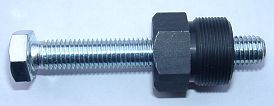 |
Um den neuen Rotor wieder abzuziehen benötigen Sie einen Abzieher M27x1,25 (Teil 99 99 799
00 -Nicht im Lieferumfang!-).
ACHTUNG: Bei Verwendung eines Klauenabziehers lösen sich die Magnete im Rotor! |
|
|
|
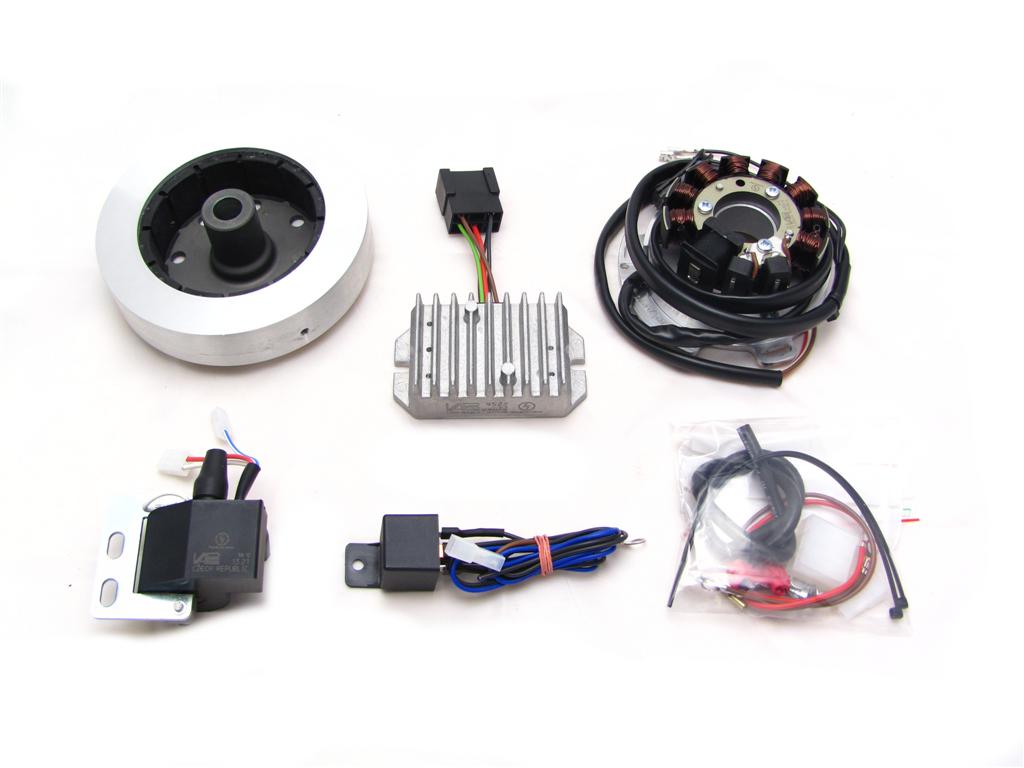 |
Diese Teile sollten Sie erhalten haben:
|
|
|
|
| Stellen Sie sicher, dass Ihre NSU fest, vorzugsweise auf einer erhöhten Montageplattform steht und Sie guten Zugang zur Lichtmaschinenseite haben. | |
|
|
|
 |
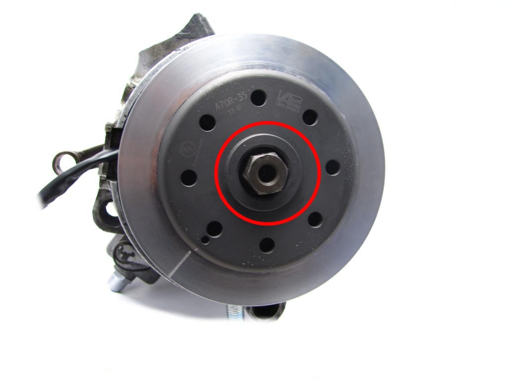
Lösen Sie alle zur alten Lichtmaschine
und der Zündspule führenden Kabel und entfernen Sie diese Teile.
Entfernen Sie bitte auch die Paßfeder an der Kurbelwelle. Sie wird nicht mehr benötigt und stört im weiteren Montageverlauf. Zum Abschrauben der Rotormutter benutzen Sie bitte das Originalwerkzeug. Sollte dieses nicht vorhanden sein, benutzen Sie einen leicht angeschliffenen Rohrsteckschlüssel SW 19.
|
|
|
|
|
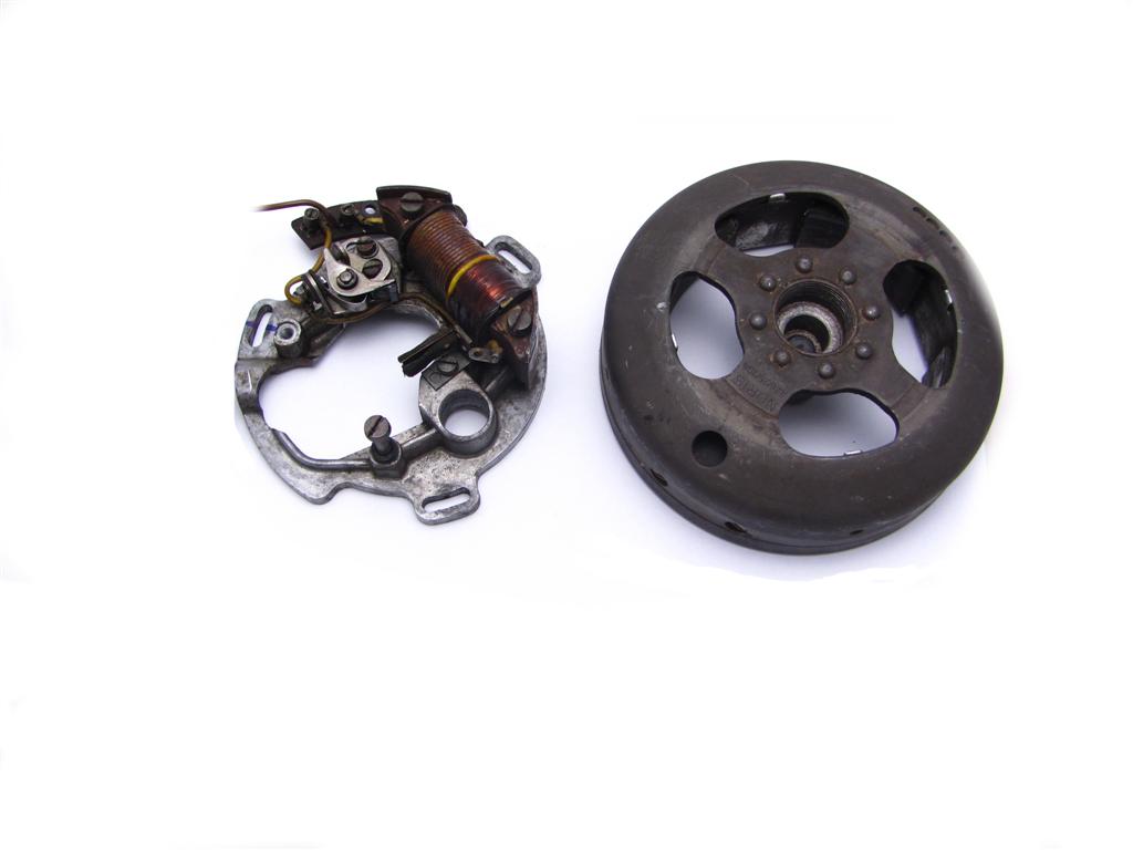
Nachdem Sie die alte Elektrik entfernt haben, sollte Ihr Motor wie folgt aussehen. |
|
|
|
|
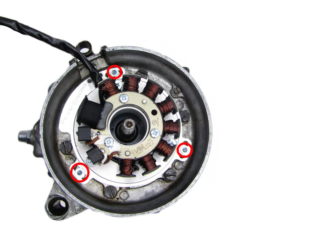 |
Setzen Sie die Statoreinheit an den Platz der alten Lichtzündanlage. Der Kabelbaum zeigt in Richtung Kabelausgang. Verschrauben Sie die Statoreinheit mit drei M5x10 + Unterlegscheibe (Im Lieferumfang). |
|
|
|
|
Zündungseinstellung: Zur größtmöglichen Flexibilität der Zündeinstellung wurde auf eine Anpassung des Rotors auf der Kurbelwelle per Paßfeder und Nut verzichtet. Es besteht dennoch (wenn der Konus korrekt ist) keine Gefahr eines unbeabsichtigten Lösens oder Verdrehens des Rotors, der ohnehin stets durch den Konus, nie durch die Paßfeder gehalten wurde/wird. Dieser hat nur eine Führungsfunktion zum Aufsetzen des richtigen Zündzeitpunktes. |
|
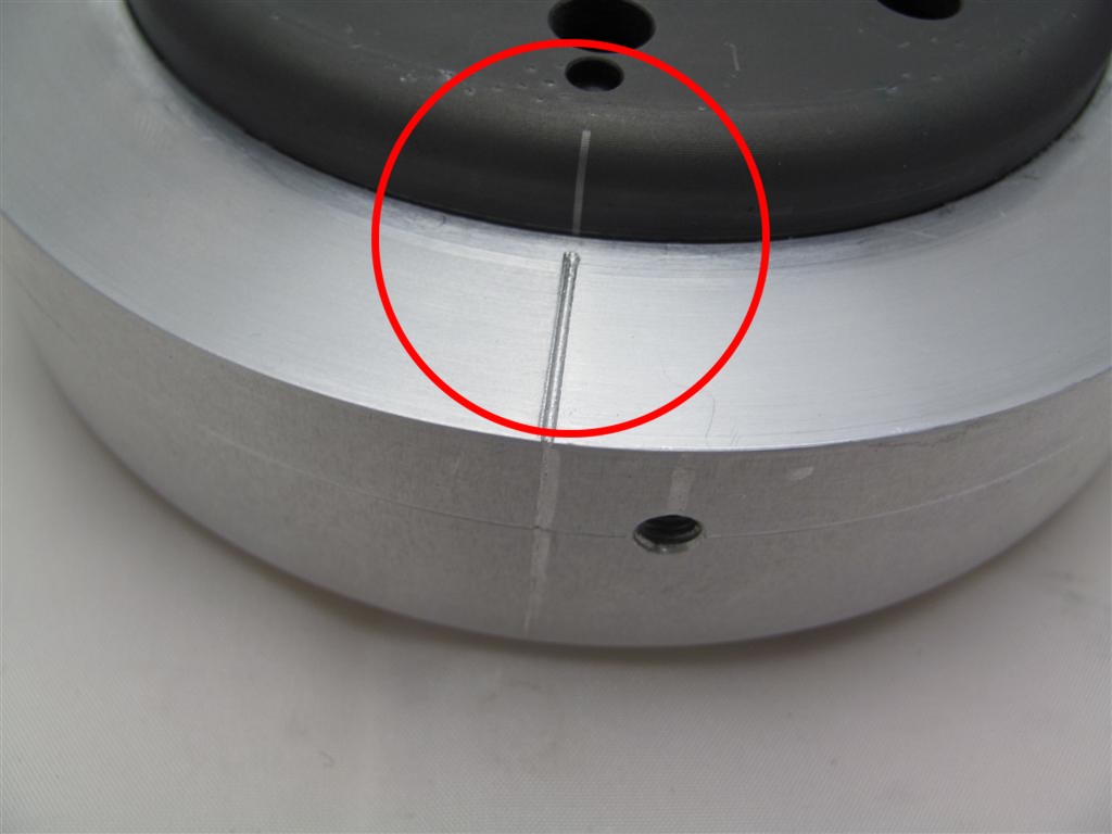 |
Sehen Sie sich den neuen Rotor an. Auf seinem Umfang finden Sie eine eingestanzte Kerbe. Das ist eine Zündeinstellmarke. |
|
|
|
|
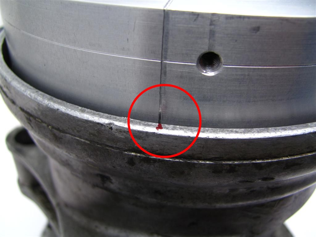
Sehen Sie sich die Statorplatte an. Auch sie hat eine Zündmarkierung
(Strich)
Diese übertragen Sie, wie auf dem Foto zu sehen, bitte auf das
Motorgehäuse. Bitte beachten: Es besteht für Sie kein Grund den Stator von der Grundplatte zu lösen. Sie laufen nur in Gefahr beim erneuten Zusammenbau Kabel einzuklemmen. |
|
|
|
|
Prüfen Sie vor dem Aufsetzen des Rotors ob dessen Magneten nicht
irgendwelche Schrauben oder andere Kleinteile aufgesammelt haben, die dann
Schaden anrichten könnten.
Stecken Sie den neuen Rotor zum Drehen der Kurbelwelle handfest auf. Sie können damit die Kurbelwelle drehen. |
|
|
|
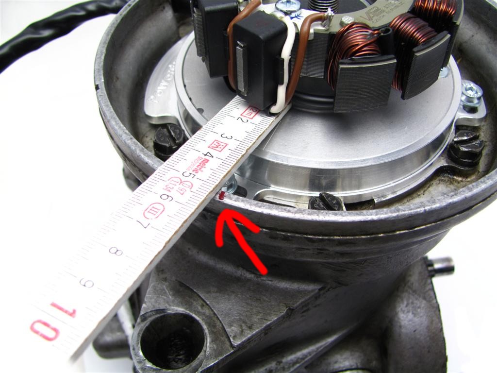
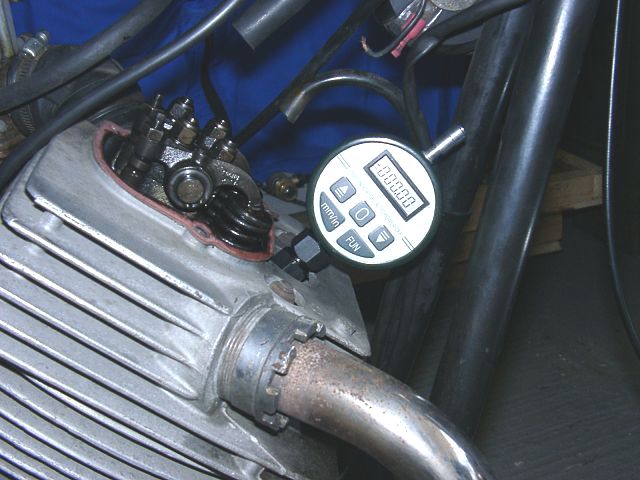
Zum Messen der Kolbenposition benötigen Sie ein Werkzeug (eine Meßuhr
oder einen Meßstab, den man z.B. aus einer alten Zündkerze anfertigen
kann. Zur großen Not geht aber auch ein Bleistift und etwas
Augenmaß).
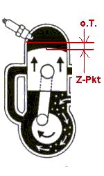
Entfernen Sie die Zündkerze und bringen Sie den Kolben in den oberen Totpunkt (hier 0.T.). Das ist die höchste Stellung, die der Kolben im Zylinder erreichen kann. Da das Polrad bei diesem System im Lauf, gegen Uhrzeigerrichtung dreht, müssen Sie es jetzt etwas in Uhrzeigerrichtung drehen, bis der Kolben auf das notwendige Maß der Frühzündung abgesunken ist. |
| Den Wert dafür entnehmen Sie bitte Ihrem Handbuch (wenn keine Werte zur Verfügung stehen, probieren Sie es mit 4mm vor OT, beschaffen Sie sich dann aber unbedingt die korrekten Werte und korrigieren Sie die Einstellung entsprechend). Falsche Einstellungen führen zu Überhitzung, im Extremfalle sogar zum Durchbrennen des Kolbenbodens. | |
|
|
|
 |
Wenn Sie die Zündposition gefunden haben, nehmen Sie den neuen Rotor
vorsichtig wieder ab und stecken Sie ihn wieder so auf, daß die
Markierung auf der Außenseite des Rotors auf Höhe der Markierung die Sie
auf das Gehäuse gesetzt haben zeigt.
Es muss eine Linie ergeben !!!
|
|
|
|
|
Verschrauben Sie den Rotor mit der originalen Befestigungsmutter.
|
|
|
|
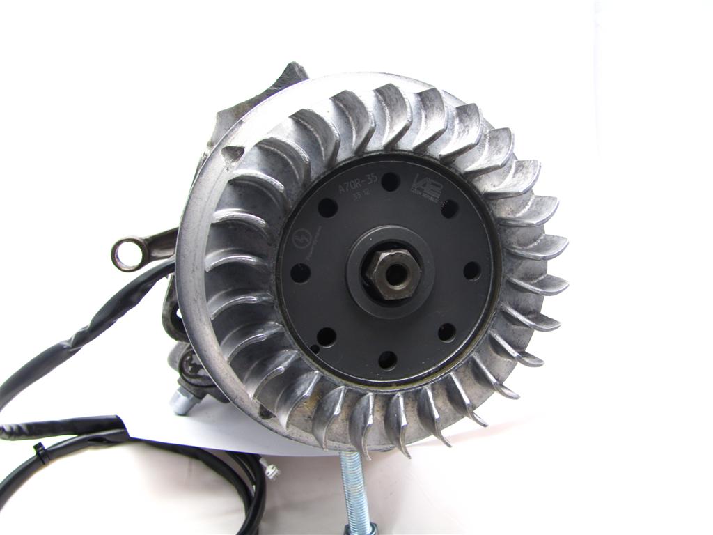 |
Setzen Sie anschließend das Original Lüfterrad auf den Rotor und befestigen Sie dieses mit den mitgelieferten vier M5x12 Schrauben.
|
|
|
|
| Befestigen Sie nun die neue Zündspule und den neuen Regler an einem geeigneten Ort. Zweckmäßigerweise mit an der Halteschelle der Zündspule. Lassen Sie eine der Halteschrauben der Zündspule noch locker, hier kommt noch ein Massekabel drauf. Verlegen sie das neue Lichtmaschinenkabel mit Hilfe der beiliegenden Kabelbinder so am Rahmen, daß es mit allen Kabeln auf Höhe Regler/Zündspule endet. Achten Sie darauf, daß nichts scheuern kann. | |
|
|
|
|
|