Powerdynamo brings new ignition & light
to your vintage motorcycle
![]()
![]()
|
|
Powerdynamo brings new ignition & light |
|
|||
|
|
|||||
|---|---|---|---|---|---|
| Einbauanleitung für Bausatz Zündanlage 74 14 599 00 |
Version 14.08.2012 |
|---|
|
If you can install your stock dynamo/alternator and
possess basic mechanical skills, you can install a Powerdynamo! |
|
| Powerdynamo can not monitor the compliance to those instructions, nor the conditions and methods of installation, operation, usage and maintenance of the system. Improper installation may result in damage to property and possibly even bodily injury. Therefore we assume no responsibility for loss, damage or cost which result from, or are in any way related to, incorrect installation, improper operation, or incorrect use and maintenance. We reserve the right to make changes to the product, technical data or assembly and operating instructions without prior notice. | |
|
|
Designated use This system is designated to replace stock ignition systems in vintage and classic motorcycles whose engine characteristics have not been modified aftermarket. This system is not a tuning system and it will not bring significant increases in engine output. It does however significantly enhance roadworthiness and road safety by offering increased reliability compared with the aging stock systems . As our systems do not tamper with engine characteristics they do not increase emission of gassous pollutants and noise. In most cases emission of pullutants should be even reduced due to better combustion. If used as designated the system therefore will not normally infringe the existing legal status of the motorcycle (this statement is valid for Germany, as this situation might be different in other countries, please consult your local road licencing regulations). This system is not suitable for use in competition events. If used other than designated warranty is voided and it might well be that you do not obtain the desired results. In worst cases use not in accordance with designated use might entail legal roadunworthiness. |
| Please read these instructions fully and carefully before starting work on your motorcycle. Please bear in mind that any modification of the material as well as own repair attempts which have not been agreed with Powerdynamo may result in a loss of warranty. Also, please take note of the information provided on the information page for this system. Check that what you have bought really corresponds to the motorcycle you have. Wrong ignition settings may damage your engine and even hurt you during kickstart (violent kickbacks). Be careful during the first test runs. If needed change settings to safer values (less advance). | |
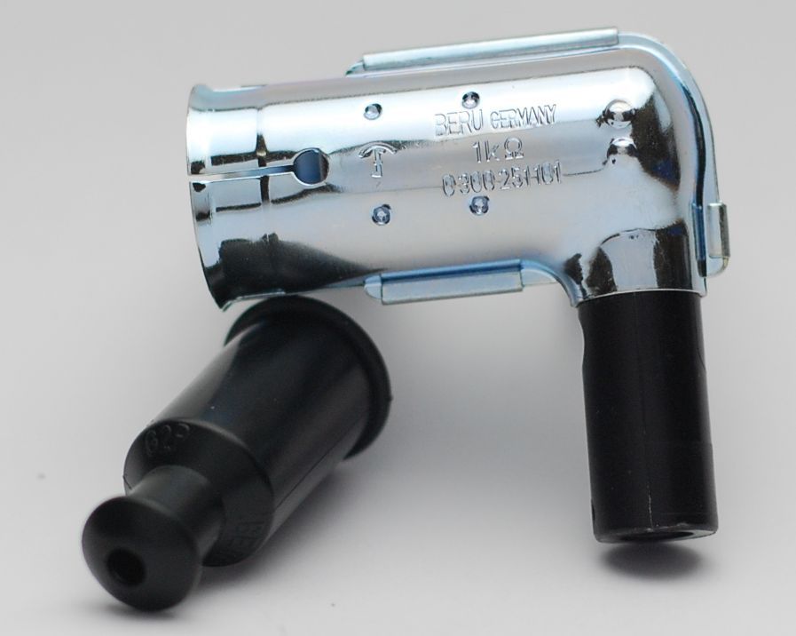
| Please always use shielded spark plug caps (but not more than 5Kohm) with this system as the hall trigger element is very sensible and may catch the emission of a spark which can lead to ignition disturbances, even failure. | |
| Never place converter and advance unit (same housing) back to back, even as this might sound convenient. It can result in ignition failure, even destruction of material due to interference | |
| Our systems are NOT tested for use with other electronic devices (such as GPS, mobile phones, other 3rd party material.) and may cause damage to such parts. Possibly existing electronic tachometers will not work with the new system. Possibly existing safety switches and electronic valve controls are not supported. It might be that your motorcycle was originally equipped with an ignition that did limit top speed for legal reasons. The new system does not have such a facility, so check your legal situation beforehand | |
| If you have no expertise for the installation have it done by an expert or at a specialist's workshop. Improper installation may damage the new system and your motorcycle. | |
|
|
If you have access to the Internet, best view those instructions online. You get larger and better pictures by clicking onto them and possibly updated information. System list at http://www.powerdynamo.biz |
|
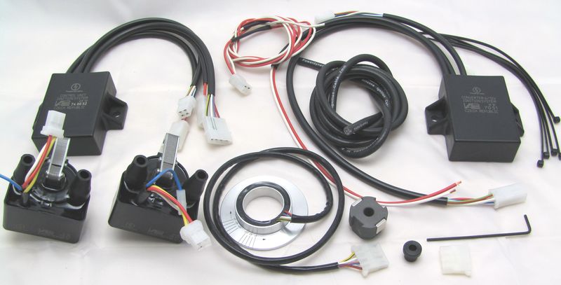
Diese Teile sollten Sie erhalten haben:
|
|
Dies ist ein Bausatz, der alle elektronischen Komponenten enthält,
für den aber mechanische Anpassungen an den Hallrotor (Innenbohrung) und
den Hallsensor (Adapter und Anpassung des Durchmessers des Hallgebers)
durch den Kunden erfolgen müssen. Für eine Reihe von (in der Zahl wachsenden Anwendungen) bieten wir bereits komplett konfektionierte Systeme an, für deren Einbau nur der vorhandene Verteiler entkernt und teilweise kleine neue Bohrungen für die Befestigung des Adapterseingebracht werden müssen. Alles andere ist bei den konfektionierten Systemen passfertig - bei dem Bausatz hier noch nicht. |
|
|
|
|
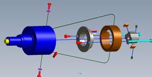
Kurzbeschreibung des Einbaus: Der Geberring wird in den zuvor entkernten Verteiler gesetzt und dort verschraubt und der Verteiler wieder am Motor wie original befestigt. Konverter, Steuereinheit und Zündspulen werden geeignet am Fahrzeug befestigt. Zündeinstellung über definiertes Aufsetzen des Hallrotors auf die Welle (siehe weiter Unten) |
|
|
|
|
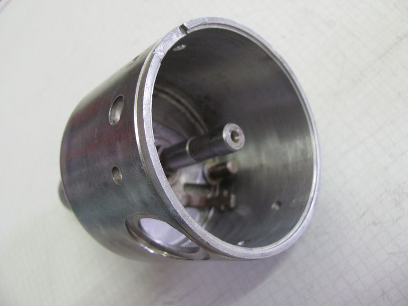 |
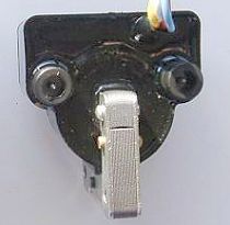
Entfernen Sie den Fliehkraftregler und den Unterbrecher aus dem Verteilergehäuse. |
|
|
|
 |
Fertigen Sie einen geeigneten Adapter um den Hallsensor im Gehäuse des Verteilers zu befestigen. Für konfektionierte Systeme ist dieser Adapter mit dem darin eingesetzten Hallgeber bereits angepasst Nehmen Sie für den Adapter bitte kein ferro-magnetisches Material, da dies Wechselwirkungen mit dem Hall bringen könnte. |
|
|
|
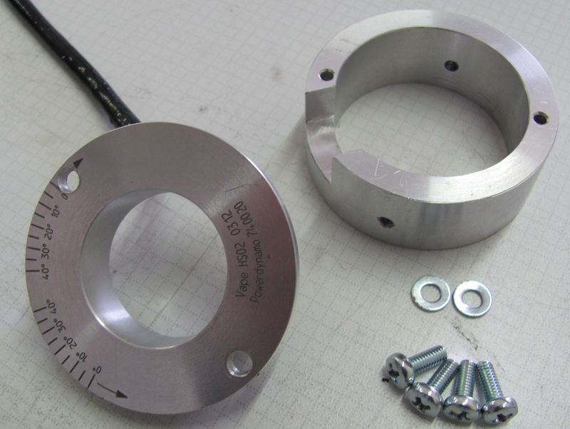 |
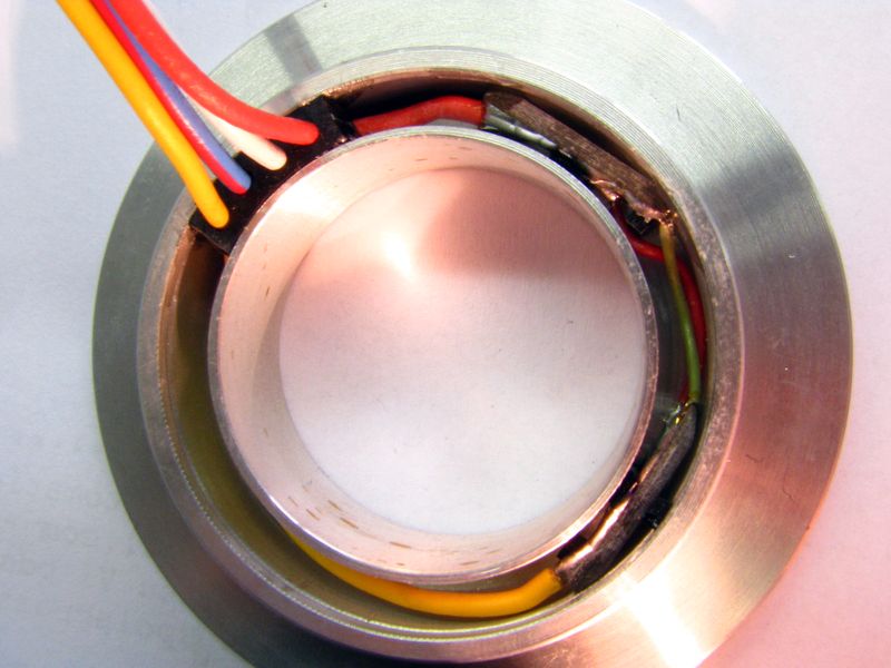
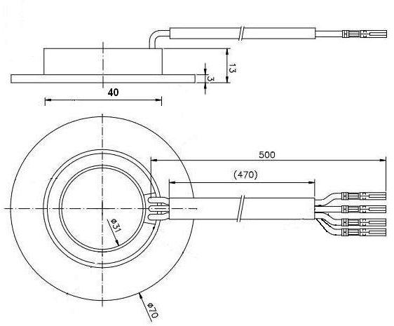
Passen Sie den Hallsensor (in Verbindung mit dem oben genannten Adapter) an die benötigten Abmessungen an. Für konfektionierte Systeme ist der Hallsensor bereits angepasst Arbeiten Sie auf keinen Fall in den vergossenen Bereich hinein, da sich darin Elektronik befindet. Sie können den Geber sowohl mit dem Kabel nach oben, als auch nach
unten einbauen. Abmessungen des Geberringes im Lieferzustand (bei Bausatzlieferung) |
|
|
|
 |
Passen Sie den Hallrotor auf der Welle an. Er wird dort mit 2 im Rotor befindlichen Madenschrauben M4 durch Klemmen befestigt. Der Rotor hat eine Bohrung von 8mm Durchmesser und kann maximal bis ca. 16mm aufgebohrt werden. Für konfektionierte Systeme ist der Rotor bereits angepasst. Der Rotor hat zwar mehrere Aufnahmen für Magnete, darf in diesem System aber nur 2 um 180 Grad versetzte Magneten haben. |
|
|
|
 |
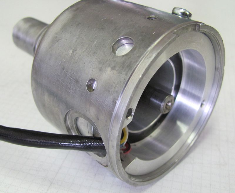
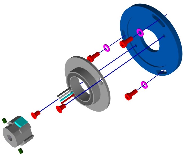
Führen Sie das Kabel der neuen Gebereinheit durch die Kabelöffnung des Verteilers. Setzen Sie den neuen Einsatz mit dem Signalsensor in den Verteiler und verschrauben Sie es dort. Setzen Sie den Geberrotor auf die Welle des Verteilers. Prüfen Sie das dieser nirgends klemmt, ziehen Sie aber seine Halteschrauben noch nicht an. Hier muss erst die Zündeinstellung wie weiter unten beschrieben erfolgen. Nach erfolgter Einstellung befestigen Sie den Rotor durch Anziehen der beiden Schrauben. Achten Sie dabei darauf die Zündeinstellung nicht zu verändern. |
|
|
|
|
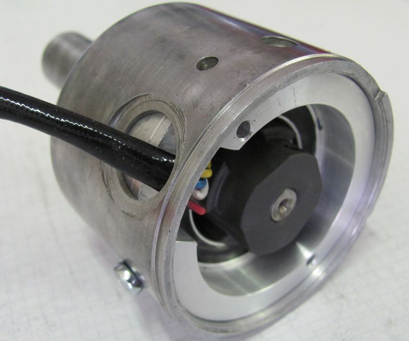
In dem umgearbeiteten Verteiler befindet sich jetzt der doppelte
Hallsensor (90 Grad versetzt) sowie der Geberrotor mit den zwei
Magneten. Jeder der Hallsensoren steuert eine Zündspule an. Damit zünden nie beide gleichzeitig, es werden unnütze Funken vermieden. Die Zündung erfolgt alle 180 Grad Kurbelwelle (90° Nockenwelle) |
 |
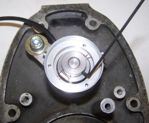
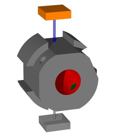
(vereinfachtes Bild) Setzen Sie jetzt den Rotor locker auf die Welle. Achten Sie darauf, dass die beiden kleinen Madenschrauben nicht zu weit eingeschraubt sind und der Rotor nicht ganz über die Welle geht. Der Rotor sollte ungefähr so tief sitzen, dass der Magnet vollständig im Hallsensor sitzt (siehe Bild links). Nehmen Sie nun die unten erläuterte Einstellung der Zündung vor. Danach müssen Sie den Rotor mit den beiden Madenschrauben festziehen. |
|
|
|
| The system composed with this hardware is a 6 or 12V battery based high energy condenser discharge ignition (CDI) to be fitted at camshaft level (distributer) in 4 cylinder 4 stroke parallel engines (not V types). There are 2 twin ignition coils, each of them individually firing both lines once every crankshaft revolution. Between the 2 twin coils are 180 degrees crankshaft difference. | |
|
|
|
|
You may consult the wiring described below in graphic form in wire diagram 7414 |
|
|
|
|
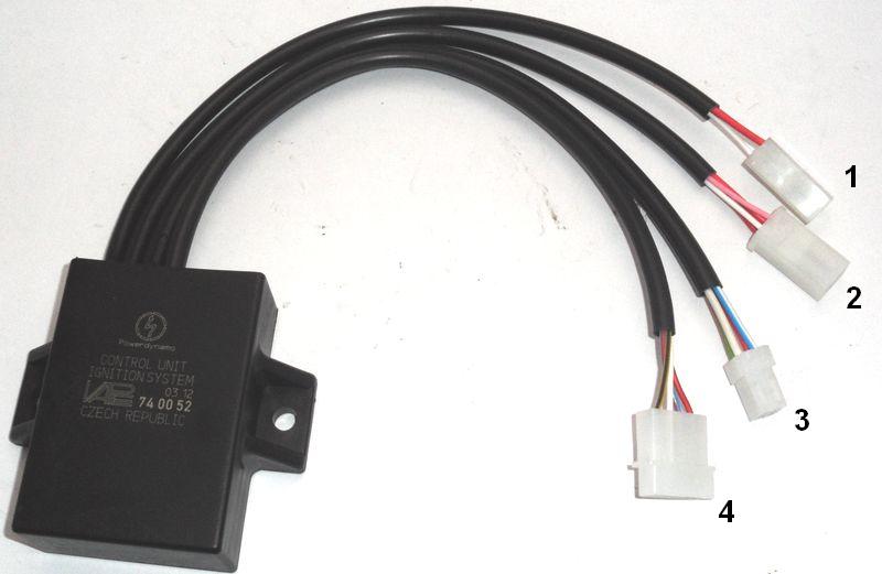
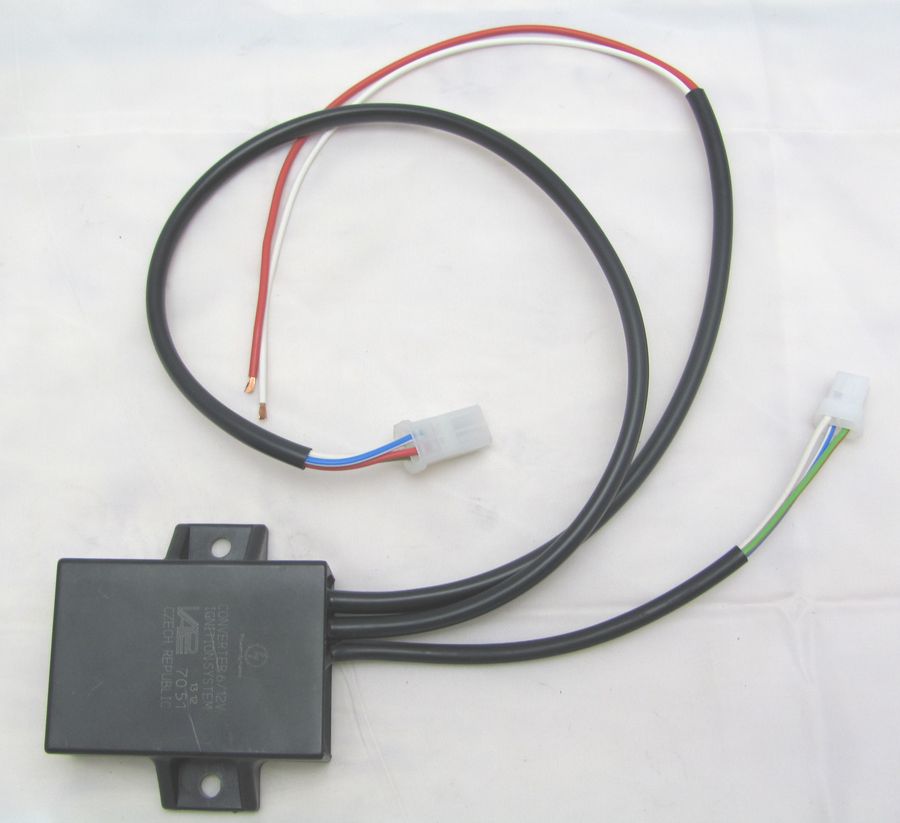
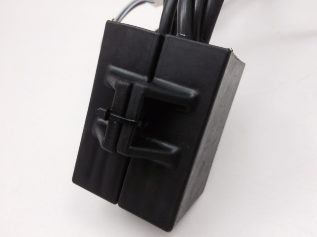
| First, get to know the wires and plugs at the advance unit (labeled 74 00 52). | |
|
Here you have:
|
|
|
|
| Start with connecting the cable from hall-sensor unit to advance unit | |
|
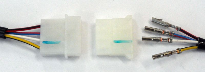
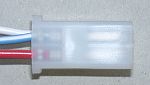
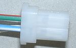
After you have ushered the wires from the hall-sensor through possible tight openings you put the flat 4 hole plug cover onto the wires from the hall sensor. Wire colours remain same. Both plug parts have some elevation to help orientation (we marked them green here for better visibility). Please double check that really colour connects to colour on both sides of the plug connection |
|
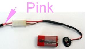
Identify the cable on the advance unit (pos 2 in overview picture)
which has a pink wire in it. You have received a cable called setup cable
with wires red and white. The plug on this cable matches the plug with the
pink wire. When you connect you match.
For setup please connect a battery 6 to 12V (may also be a 9V block as shown here). Red to plus, white to minus. Note: only for systems with negative ground! |
|
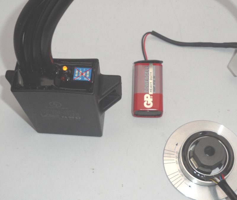
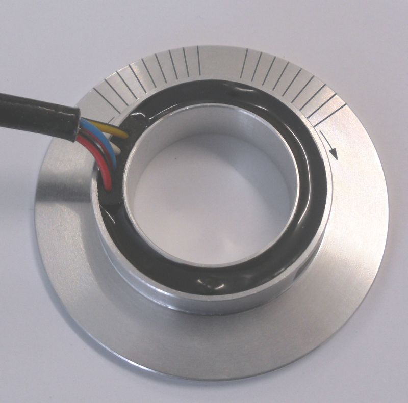
The hall unit shown here free on the table needs surely be fitted onto the
distributer at this moment. When you turn the hall rotor - still loosely
sitting on the distributer shaft and with the battery connected as
described - you will notice that at some point a diode starts shining,
than stops doing so until in the next crankshaft revolution, the next does
the same. |
|
|
|
| Now you need to set basic timing. For this, the crankshaft has to be in a position in which the piston of the first firing cylinder is 50 degrees before top dead center (TDC). Those 50 degrees have nothing to do with any engine advance, they are just some internal reference the system needs. | |
|
|
With crankshaft in mentioned 50° position of first firing cylinder and
setup wire connected you slowly turn the hall rotor into its normal
rotation direction.
Than slowly turn further into same direction until the diode so far
shining stops shining. In this position (with crank still at the
mentioned 50° situation) fasten the hall rotor on the shaft with the 2
small screws and the hex key. |
|
|
|
|
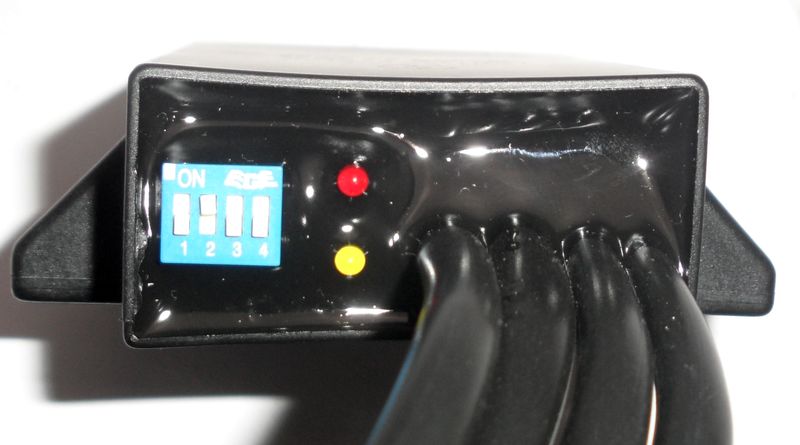
Setting the diverse characteristics (advance in relation to engine revs)
is done by setting the 4 small switches in the blue switch block on the
advance unit as indicated in the respective instructions. |
|
|
|
|
This system uses 2 twin ignition coils. Each of them firing once every
crankshaft revolution both exits at the same time (say cylinder 1 and 3)
what produces on one cylinder a so called wasted, but harmless spark. Please observe that those twin coils have a few pecularities, notably that ignition can only correctly work if both exits are connected. You can not test one by disconnecting the other as each side draws ground from the other. For testing you need to ground the non tested side (see info) The twin coil does have a short blue wire on it which in this configuration remains free (do not connect anything there!) |
|
|
|
| Take the setup cable off and connect the ignition coils as indicated above. | |
|
|
|
| Now, get to know the cables and plugs at the converter, labeled 7051. | |
|
From the converter box come 3 wire bundles
|
|
|
|
| The cable with the open wires red and white: | is for connection to the battery. Connect the white to minus of the battery and the red to plus of the battery - via the main switch. Include a 5A fuse and always run the wire via the main switch. Otherwise you can not stop the engine and you will drain your battery during longer standstills. |
|
|
|
 The
cable with the male 4 hole plug
... The
cable with the male 4 hole plug
...
|
... you connect to plug 3 of the advance unit.
colour matches colour.
|
|
|
|
 the
cable with the female 4 hole socket ... the
cable with the female 4 hole socket ...
|
... remains free (do not connect anything here, cover the plug with tape) |
|
Finally - and before you connect the battery- carefully
check again all wiring and fastening. |
|
|
|
|
|
|
|||||||||||||||||||||||||||||||||
| Jetzt müssen Sie noch die gewünschte Zündkurve
einstellen: |
|||||||||||||||||||||||||||||||||
|
Diese würden wir Ihnen entsprechend Ihrer Vorgaben mitteilen. Bei dieser beispielhaften Schalterstellung mit Schaltern OFF-ON-OFF-ON wie links gezeigt verstellt die Einheit von 10° beim Start auf 20° bei 1200 und 42° bei 2200 U/min. |
||||||||||||||||||||||||||||||||
|
|||||||||||||||||||||||||||||||||
|
|
|||||||||||||||||||||||||||||||||
|
|