Powerdynamo brings new ignition & light
to your vintage motorcycle
![]()
![]()
|
|
Powerdynamo brings new ignition & light |
|
|||
|
|
|||||
|---|---|---|---|---|---|
| assembly instructions for System 74 03 599 00 |
Version 08.11.2010 |
|---|
|
If you can install your stock dynamo/alternator and
possess basic mechanical skills, you can install a Powerdynamo! |
|
| Powerdynamo can not monitor the compliance to those instructions, nor the conditions and methods of installation, operation, usage and maintenance of the system. Improper installation may result in damage to property and possibly even bodily injury. Therefore we assume no responsibility for loss, damage or cost which result from, or are in any way related to, incorrect installation, improper operation, or incorrect use and maintenance. We reserve the right to make changes to the product, technical data or assembly and operating instructions without prior notice. | |
|
|
Designated use This system is designated to replace stock ignition systems in vintage and classic motorcycles whose engine characteristics have not been modified aftermarket. This system is not a tuning system and it will not bring significant increases in engine output. It does however significantly enhance roadworthiness and road safety by offering increased reliability compared with the aging stock systems . As our systems do not tamper with engine characteristics they do not increase emission of gassous pollutants and noise. In most cases emission of pullutants should be even reduced due to better combustion. If used as designated the system therefore will not normally infringe the existing legal status of the motorcycle (this statement is valid for Germany, as this situation might be different in other countries, please consult your local road licencing regulations). This system is not suitable for use in competition events. If used other than designated warranty is voided and it might well be that you do not obtain the desired results. In worst cases use not in accordance with designated use might entail legal roadunworthiness. |
| Please read these instructions fully and carefully before starting work on your motorcycle. Please bear in mind that any modification of the material as well as own repair attempts which have not been agreed with Powerdynamo may result in a loss of warranty. Also, please take note of the information provided on the information page for this system. Check that what you have bought really corresponds to the motorcycle you have. Wrong ignition settings may damage your engine and even hurt you during kickstart (violent kickbacks). Be careful during the first test runs. If needed change settings to safer values (less advance). | |
| Please always use shielded spark plug caps (but not more than 5Kohm) with this system as the hall trigger element is very sensible and may catch the emission of a spark which can lead to ignition disturbances, even failure. | |
| Never place converter and advance unit (same housing) back to back, even as this might sound convenient. It can result in ignition failure, even destruction of material due to interference | |
| Our systems are NOT tested for use with other electronic devices (such as GPS, mobile phones, other 3rd party material.) and may cause damage to such parts. Possibly existing electronic tachometers will not work with the new system. Possibly existing safety switches and electronic valve controls are not supported. It might be that your motorcycle was originally equipped with an ignition that did limit top speed for legal reasons. The new system does not have such a facility, so check your legal situation beforehand | |
| If you have no expertise for the installation have it done by an expert or at a specialist's workshop. Improper installation may damage the new system and your motorcycle. | |
|
|
If you have access to the Internet, best view those instructions online. You get larger and better pictures by clicking onto them and possibly updated information. System list at http://www.powerdynamo.biz |
|
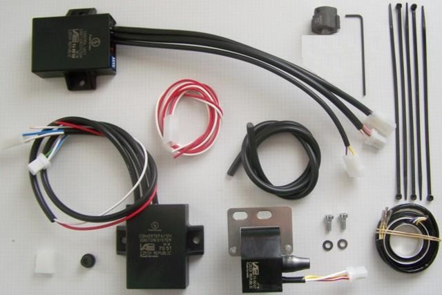
You should have received those parts:
|
|
|
|
|
Preparations: Make sure your bike rests securely on her centre stand, preferably on an elevated work bench and that you have good access to the front of the engine. You will have to turn the front wheel from side to side for good access. Disconnect your battery and take it out of the motorcycle for the time of work. Drain the petrol (gas) from the tank into a canister. Take care not to spill any petrol and refrain from smoking. Disconnect the tube running between the tanks sides under the frame tube. Take the petrol tank off the bike and put it to a secure place for the time of work at the bike. |
|
|
|
|
Overview of assembly: Instead of the points plate and the Bowden cable shifting (the Bowden cable may remain for optical reasons) will be mounted a Hall sensor system. This consists of a carrier ring with a built-in sensor and a magnet-based trigger unit mounted on a shaft. The function of the Bowden-cable regulation is replaced by an electronic advance unit. The CDI ignition coil requires a charging voltage of 340 volts. This will be obtained via a converter from the battery voltage of 6 volts. Without battery does not work the ignition. Assembly: |
|
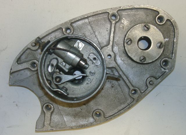 |
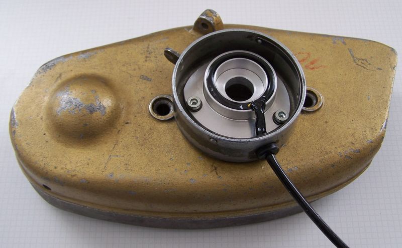
Remove the complete breaker unit from the cam shaft. Remove the points and the capacitor from the distributor housing. This housing will not rotate anymore. |
|
|
|
|
Clean the hole in the camshaft. There the shaft of the new rotor will be
glued-in.
Before you glue, check if the pin is sitting in a correct way to hold the magnet rotor so that its upper edge aligns with the upper edge of the sensor plate. |
|
|
|
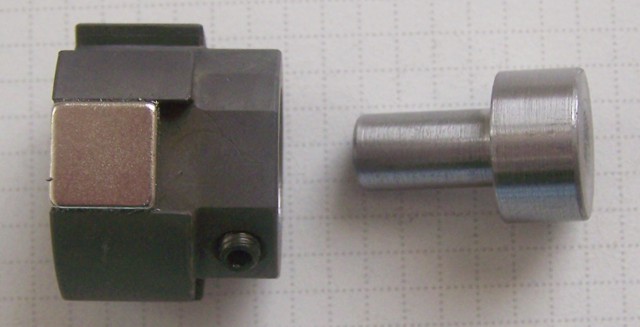 |
The rotor will mounted with two hollow set screws M4 (a appropriate Allen-key is provided). |
|
|
|
 |
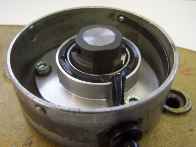
Lead the cable of the new Hall sensor through the opening of the
distributor case. Secure the cable with the grommet provided.
Screw the sensor plate with the original mounting screws and a washer. Now the bushing may not be longer rotatable. |
|
|
|
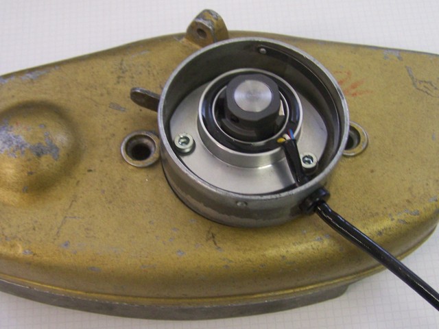 |
When the glue has cured, place the magnet rotor on the shaft. Tighten the two screws but not yet fixed, the height of the rotor must be adjusted yet. |
|
|
|
| Before you screw the magnetic trigger on the
camshaft, you have to get the crankshaft to a position 50░ BTDC. This are 15.27mm piston
travel, which is about 15mm BTDC.
Note: This is not the ignition adjustment (this is on the R35 40░ BTDC), but a basic adjustment on this new material. Remove the spark plug and bring the piston (in compression stroke) to 15mm BTDC. |
|
|
|
|
|
initial positioning of crank shaft |
|
|
The advance units needs a basic reference to work
on. As explained before, it changes a range, not absolute values (of
degrees). Standard basic setting is with the crankshaft in a position of 45 degrees before top dead center (TDC) of a piston (any of the 3 pistons, it always fires all 3 at the same time). For this position the values indicated above are true. Wehen you set the shaft not in 45, but only 40 degrees (which we presently think might be better) than you change from 2 to 23 degrees. . |
|
|
wiring and positioning of the magnetic rotor |
|
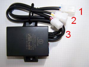
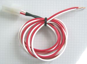
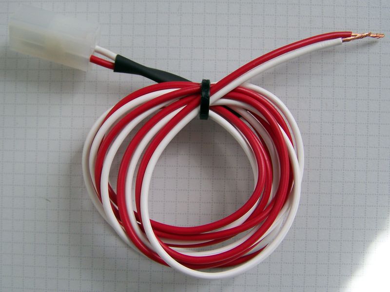
| Take the advance unit (marked 740050) and the (separate) red and white timing setup wire. | |
|
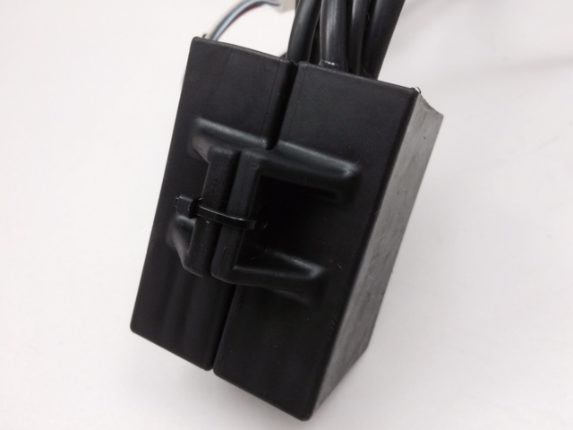
the advance unit has 3 plugs:
Note: the advcance unit is housed in an box identical to the one of the
converter, but contains something quite different. The advance box is
labelled 740050.
|
| For timing the converter may, but need not connected on plug 1.. | |
|
plug 2:
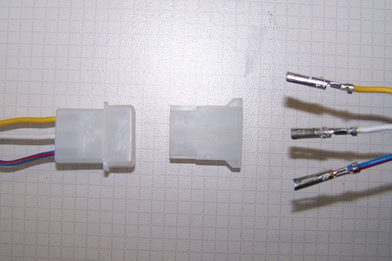
The 3 wires from the hall element inside the points housing are connected via this plug to the advance. We have not placed the plastic housing over the wire ends to facilitate wire exit from the points housing. Please make absolutely sure that you connect:
|
|
plug 3:
is only used for setting up timing.During normal use it remains idle (better cover
against dirt and water)
red connects for timing to plus 12V, white to minus (ground) |
picture shows different installation |
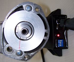
With the above red and white wires connected to a battery 12V (red =
plus, white = minus):
Loosen the provisionally fastened magnetic rotor so that it can be
turned on the shaft without changing crank position. |
|
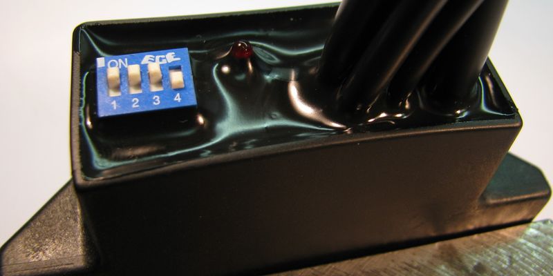
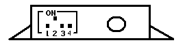
On top of the advcance unit you find a blue switch block. You need to set the switches as indicated in those instructions. Neither the situation in the picture here, nor the setting it arrives with are correct. The switches acticvate different advance curves. |
|
|
|
|
|
|
|
The curve made for this system is activated by switch 2 to ON and switches 1,3,4 away from ON (that is OFF). It gives 2░ from start up to 1.000rpm and than gradually opens to a full 40░ at 3.000rpm. |
|
|
|
| Now the system has to be wired: | |
|
Wiring after ignition timing |
|
|
Connect all wires as shown in wiring diagram 74599-1 : |
|
| Voltage converter "7051": | |
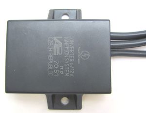
|
There are three cable looms at the converter:
|
| The cable loom with the open end wires: | Connect the white wire (ground) to the negative battery pole and the red wire (positive) to the positive main switch (necessarily with a 10 ampere fuse). |
 the
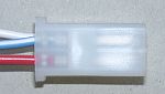
cable loom with the male quadruple socket: the
cable loom with the male quadruple socket:
|
connect to the suitable (female) socket of the
wiring loom to the ignition coil. Attention, some colours are changing now:
|
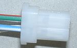 the
cable loom with the female quadruple socket: the
cable loom with the female quadruple socket:
|
connect to the suitable socket of the control unit (socket 1, see above).
Attention, some colours also changing:
|
|
Please re-check (before you connect the battery and start
the bike) all fixtures and wiring carefully. |
|
|
|
Important safety and operating information |
|
# |
Safety first! Please observe the general
health and safety regulations motor vehicle repair (MVR)
as well as the safety information and obligations indicated by the
manufacturer of your motorcycle. The timing marks on the material are for general guidance only during first installation. Please check after assembly by suitable means (stroboscope) that settings are correct to prevent damage to the engine or possibly even your health. You alone are responsible for the installation and the correctness of settings. |
|
# |
Ignition systems generate high tension! With our
material right up to 40,000 Volts! This may, if handled carelessly, not
only be painful, but outrightly dangerous.
Please do keep a safe distance to the electrode of your spark plug and
open high tension cables. Should you need to test spark firing, hold the
spark plug socket securely with some well insulating material and push
it firmly to solid ground of the engine block. Never pull sparkplug caps when engine is running. Wash your vehicle only with engine at standstill and ignition off. |
|
# |
Should you have received in the kit HT cables with a fixed rubber boot(which does not contain a resistor) you might have to use spark plugs with an inbuilt resistor (or replace the cap with one containing a resistor) to comply with your local laws. |
|
# |
After installation, please check tightness of all screws, even those preinstalled. If parts get loose during run, there will be inevitably damage to the material. We pre-assemble screws only loosely. |
|
# |
Give the newly installed system a chance to work, before you start
to check and test values, or what is worse apply changes to it. Our parts have been checked before delivery to you. You will not be able to check much anyway. At any rate do refrain from measuring the electronic components (such as ignition coil, regulator and advance unit). You risk severe damage to the inner electronics there. You will not get any tangible results from the operation anyway. Bear in mind that also your carburetor, your spark plugs and spark plug sockets (even if completely new) might be the reason for malfunction. The general experience with our systems is that the carburetor will have to be re-adjusted to lower settings. Should the system not start after assembly, first disconnect the blue (or blue/white) cut-off wire directly at the ignition coil (or in some cases advance unit) to eliminate any malfunction in the cut-off circuitry. Check ground connections carefully, make sure there is a good electrical connection between frame and engine block. In case of troubles, please consult our Knowledge Base first before you send off the material to us for checking |
|
# |
The spark of classic, points based ignition systems has with about 10,000 Volts comparatively little energy and looks therefore yellow and fat (which however makes it highly visible). The spark from our system is a high energy spark with up to 40,000 Volts and therefore is needle thin focused in form, and blue in colour, which makes it not so visible. Furthermore you get spark only at kick-start operated speeds and not by pushing the kick-lever down slowly with your hand (as you might get with battery based ignitions). |
|
# |
Systems using a twin outlet ignition coils have a few peculiarities. Please observe that during tests on one side, the other has either to be connected to an fitted spark plug or securely earthed/grounded. Otherwise there will be no spark on either side. Also with such open exits long and dangerous sparks may fly all over the coil. |
|
# |
Never do electric arc welding on the bike without completely disconnecting all parts containing semiconductors (ignition coil, regulator, advance) stator and rotor need not be taken off. The same is true for soldering. Before touching electronics disconnect the soldering iron from mains! Never use copper putty on spark plugs. |
|
# |
Electronics are very sensitive to wrong polarity. After work on the system, do check correct polarity of the battery and the regulator. Wrong polarity creates short circuits and will destroy the regulator, the ignition coil and the advance unit. As a rule, wiring will always be colour to colour. Instances, where colour jumps between wires are expressly mentioned in our instructions. |
|
# |
When you handle the new rotor, take care not to damage its magnets. Refrain from direct blows to the circumference of the rotor. When transporting never put the rotor over the stator. Observe our information relative to transport of the material. |
|
# |
Do not use spark plug sockets with a resistance of more than 5kOhm. Better use 1 or 2kOhm ones. Bear in mind that spark plug sockets do age and thereby increase their internal resistance. Should an engine start up only when cold, a defective spark plug socket and/or spark plug is very probably the cause. In case of problems check high tension cables too. Never use carbon fibre HT-cables, never use so called "hot wires" which promise to increase spark. |
|
# |
It is a good idea to cover the rotor in a thin layer of oil to reduce the risk of corrosion. |
|
# |
Never use a claw puller or a hammer to disengage the rotor. Its magnets might become loose in the event. We offer a special puller for disengaging the new rotor again (see assembly instruction)! |
|
# |
Should the motorcycle not be in use for some longer period, please disconnect the battery (so existing) to prevent current bleeding through the diodes of the regulator. Though, even a disconnected battery will empty itself after a while. |
|
# |
Please do observe these remarks, but at the same
time, don't be afraid of the installation process. Remember, that before you, thousands of
other customers have successfully installed the system. Enjoy driving your bike with its new electric heart! |
|
|