Powerdynamo brings new ignition & light
to your vintage motorcycle
![]()
![]()
|
|
Powerdynamo brings new ignition & light |
|
|||
|
|
|||||
|---|---|---|---|---|---|
| assembly instruction for system 72 85 799 DC |
Version 18.048.2016 |
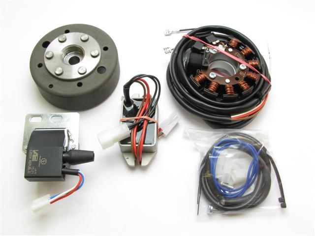 |
You should have received those parts:
|
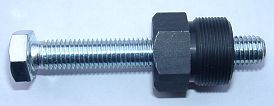 |
To disangage the new rotor again, you need a puller M27x1,25 (part-no.: 99 99 799 00 -Not
provided!-).
Note: Never use a claw puller, a hammer or any other device, that will shake the magnets off. |
|
|
|
| Make sure your Husqvarna rests securely on her stand, preferably on an elevated work bench and that you have good access to the magneto side of the engine. | |
|
|
|
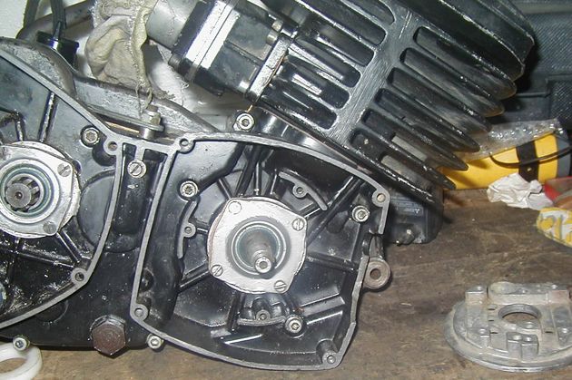 |
Disengage all cables of the old magneto and ignition coil and take these parts
off.
Take the woodruff key from the crank. You will not need it any more. Please do not forget to do so, otherwise you will have trouble later on in the assembly. (Remark: This woodruff key does not actually hold your rotor on the shaft, this is done by the taper. it simply guides to the correct setting which will now be otherwise achieved.) |
|
|
|
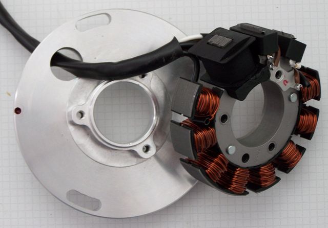 |
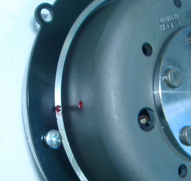
Have a look at the new stator unit. You will
find there a small red ignition marking for timing (in the picture red
encircled). Note that the stator is only loosely fixed to its base, as you will have to disengage it for assembly. |
|
|
|
|
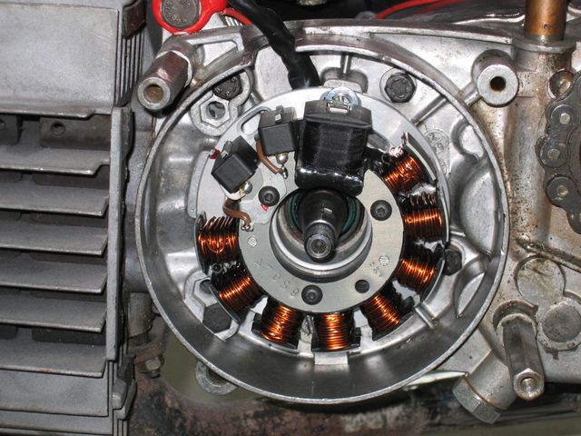
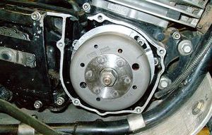
Put the base plate with the stator hanging loosely from the unit into the
place of your old generator. Fasten the plate with the 3 screws M5. Take care to not jam any wires under the
plate.
Put the stator coil back onto the plate, take care not the damage the wires. the stator has to snap in rather sharply. If it sets soft, you have probably jammed a wire underneath! Make sure that the inner opening of the stator unit slots evenly over the elevated fixing rim of the base plate - otherwise the coil will sit lopsided and will touch the rotor, damaging it. Screw the coil down with the 3 screws M4 and tighten.
(Photo shows similar engine!) |
|
|
|
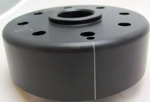 |
Have a look at the new rotor. You will find on its circumference a small pressed in line. That is an ignition marking. It is durable, but not well visible, so better highlighten it with some marker pen. |
|
|
|
|
Place the rotor loosely onto the crank and check that it may move freely
above the statorbase.
Take the spark plug out and bring the piston into ignition position. Might be 1-3.5mm BTDC. (Please do consult the manual of your motorcycle!). Remind that your Husqvarna's engine is turning clockwise. That means you have to turn the rotor counter-clockwise for adjusting BTDC!
(Photo shows similar engine!) |
|
|
|
|
Take the rotor carefully off again without changing the
crank's position and reset it onto the crank in such a way that the
marking on the rotor aligns with the marking on the stator. In that
position fasten the rotor carefully with the stock nut (left-hand
thread). Don't forget to use the original washer! Do not change the ignition position of the crank shaft during this procedure, otherwise you have to redo it. |
|
|
|
| The works at the engine are finished. Screw in the spark plugs again. | |
|
|
|
 |
Fasten the ignition coil at a convenient place, favourably near to the spark
plug.
Turn the HT-cable previously into the ignition coil. Leave one of the fastening screws loose, you have to connect a ground cable here. |
|
|
|
|
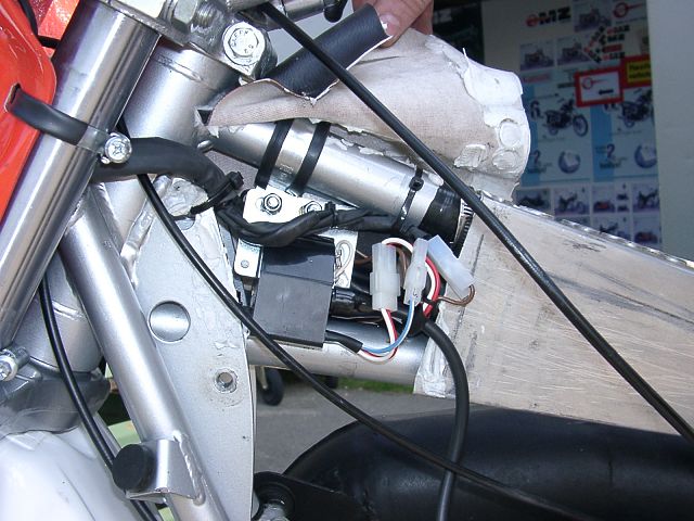
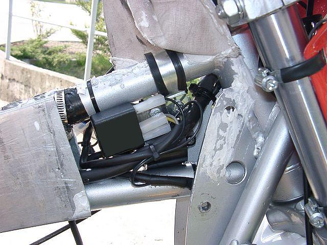
Fasten the AC-regulator on the frame of the motorcycle,
best beneath the seat or the side casing.
Lay the new generator cable in that way on the frame, that it finished close to the regulator/rectifier (resp. ignition coil) by using the enclosed cable ties. Take care, that nothing's pinched.
(Picture shows the AC-version!) |
|
|
|
|
Connect the parts as shown in wiring diagram 71ik_102: |
||
|
* |
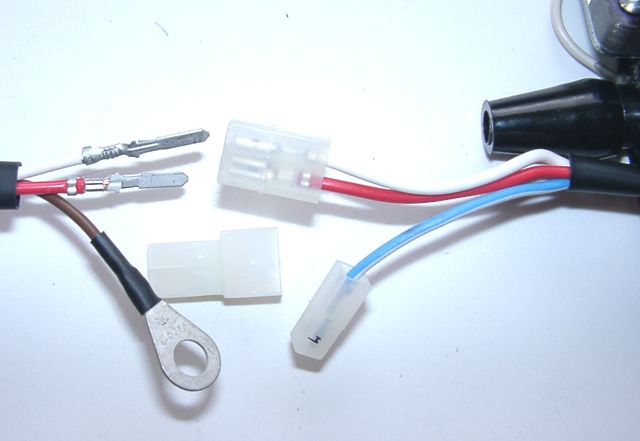
To facilitate wire exit through the often small openings in the engine casing, the plastic plug of the generator's wiring that leads to the ignition coil has not been put onto the wire terminal. You should place the plug there only once all has been properly installed on the engine side. | |
|
|
Look for the ignition coil with its female plug and the two wires (red and
white).
Put the provided 2-position plug housing onto this plug and insert the two wires (red and white) from the generator. Make sure that the terminals engage securely in the housing and that you connect:
|
|
|
Should you need (or want) to get the terminals out of the plug housing again, enter a paper clip from front next to the terminals and push the little barb aside. Than pull the wire out. |
||
|
The brown wire from the new generator with the round eye
terminal has to be screwed directly to the holder frame of the ignition coil (ground). |
||
|
* |
|
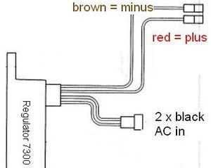
The new regulator/rectifier has 4 wires
|
| The two black cables leading from the generator ... |
... should be first introduced into the supplied twin plastic plug housing. This housing connects to the plastic plug at the end of the 2 black wires on the regulator. It does not matter which black is at which side, as there is AC. |
|
| The brown cable from the regulator ... |
... should connect to either battery minus or good ground if there is no battery. |
|
|
The red cable from the regulator ... Take care: |
... should connect to either battery 12V PLUS or if there is no battery to the wiring that runs to your consumers (normally main switch intake pin). |
|
| If you use a battery, make sure that you have a 15A-fuse between battery and vehicle circuitry. | ||
|
There is NO facility for a charge control light without battery this will not work anyway. The regulator has an inbuilt high potency condenser to smoothen voltage. This will make sure that your side indicators (flashers) and horn will work correctly even without battery. |
||
| * |
Remains the blue (sometimes blue/white) wire at the ignition coil. This is the kill (cut-off) wire.
Note: |
Connected to ground - it
will stop ignition!
This type of wiring is used in motorcycles which originally already had magneto ignition and therefore switched off by shortcircuiting against ground. Those vehicles have by design a main lock (or some kill switch) that connects a pin to ground when in OFF position (German bikes: pin 2). The blue(/white) wire of the ignition coil will be connected here. In that way the cut-off works like previously. |
| * |
Screw the high tension (ignition) cable ...
Please do not use any spark amplifying cables, such as "Nology supercables" or "hot wire". This will disturb the system and possibly damage it. |
... into the ignition coil and pull over the rubber seal before
mounting the
coil (it will be easier).
Please do use the cable arriving with the pack and not any old cable. |
|
You will do yourself a favour to treat your bike to new spark plugs and
spark plug sockets (preferably some between 0-2kOhm).
Plenty of problems are to be traced back to "apparently good" (even
completely "brand-new") sparks plugs, terminals and cables. Do not use spark plugs with an intern suppression resistor. NGK (e.g.) offered such spark plugs coded with an "R" (for resistor). |
||
|
* |
Finally - and before installing the battery and before the first kickstart - please re-check carefully all connections and fitments against the wiring diagram. Do check battery and light bulbs for correct voltage (12V). Should something not work, please consult our trouble-shooting guide on our homepage. As a first step disconnect the blue wire from the coil and re-test. |
|
| * |
IMPORTANT: During crank shaft repair the dynamo shaft is often
machined and gets shorter. The result is a rotor sitting lower, possibly
touching now with its rivets the stator coil. The result is a destroyed
stator and ignition failure. For more detail and how to check see (online) here. |
|
|
|
Important safety and operating information |
|
# |
Safety first! Please observe the general
health and safety regulations motor vehicle repair (MVR)
as well as the safety information and obligations indicated by the
manufacturer of your motorcycle. The timing marks on the material are for general guidance only during first installation. Please check after assembly by suitable means (stroboscope) that settings are correct to prevent damage to the engine or possibly even your health. You alone are responsible for the installation and the correctness of settings. |
|
# |
Ignition systems generate high tension! With our
material right up to 40,000 Volts! This may, if handled carelessly, not
only be painful, but outrightly dangerous.
Please do keep a safe distance to the electrode of your spark plug and
open high tension cables. Should you need to test spark firing, hold the
spark plug socket securely with some well insulating material and push
it firmly to solid ground of the engine block. Never pull sparkplug caps when engine is running. Wash your vehicle only with engine at standstill and ignition off. |
|
# |
Should you have received in the kit HT cables with a fixed rubber boot(which does not contain a resistor) you might have to use spark plugs with an inbuilt resistor (or replace the cap with one containing a resistor) to comply with your local laws. |
|
# |
After installation, please check tightness of all screws, even those preinstalled. If parts get loose during run, there will be inevitably damage to the material. We pre-assemble screws only loosely. |
|
# |
Give the newly installed system a chance to work, before you start
to check and test values, or what is worse apply changes to it. Our parts have been checked before delivery to you. You will not be able to check much anyway. At any rate do refrain from measuring the electronic components (such as ignition coil, regulator and advance unit). You risk severe damage to the inner electronics there. You will not get any tangible results from the operation anyway. Bear in mind that also your carburetor, your spark plugs and spark plug sockets (even if completely new) might be the reason for malfunction. The general experience with our systems is that the carburetor will have to be re-adjusted to lower settings. Should the system not start after assembly, first disconnect the blue (or blue/white) cut-off wire directly at the ignition coil (or in some cases advance unit) to eliminate any malfunction in the cut-off circuitry. Check ground connections carefully, make sure there is a good electrical connection between frame and engine block. In case of troubles, please consult our Knowledge Base first before you send off the material to us for checking |
|
# |
The spark of classic, points based ignition systems has with about 10,000 Volts comparatively little energy and looks therefore yellow and fat (which however makes it highly visible). The spark from our system is a high energy spark with up to 40,000 Volts and therefore is needle thin focused in form, and blue in colour, which makes it not so visible. Furthermore you get spark only at kick-start operated speeds and not by pushing the kick-lever down slowly with your hand (as you might get with battery based ignitions). |
|
# |
Systems using a twin outlet ignition coils have a few peculiarities. Please observe that during tests on one side, the other has either to be connected to an fitted spark plug or securely earthed/grounded. Otherwise there will be no spark on either side. Also with such open exits long and dangerous sparks may fly all over the coil. |
|
# |
Never do electric arc welding on the bike without completely disconnecting all parts containing semiconductors (ignition coil, regulator, advance) stator and rotor need not be taken off. The same is true for soldering. Before touching electronics disconnect the soldering iron from mains! Never use copper putty on spark plugs. |
|
# |
Electronics are very sensitive to wrong polarity. After work on the system, do check correct polarity of the battery and the regulator. Wrong polarity creates short circuits and will destroy the regulator, the ignition coil and the advance unit. As a rule, wiring will always be colour to colour. Instances, where colour jumps between wires are expressly mentioned in our instructions. |
|
# |
When you handle the new rotor, take care not to damage its magnets. Refrain from direct blows to the circumference of the rotor. When transporting never put the rotor over the stator. Observe our information relative to transport of the material. |
|
# |
Do not use spark plug sockets with a resistance of more than 5kOhm. Better use 1 or 2kOhm ones. Bear in mind that spark plug sockets do age and thereby increase their internal resistance. Should an engine start up only when cold, a defective spark plug socket and/or spark plug is very probably the cause. In case of problems check high tension cables too. Never use carbon fibre HT-cables, never use so called "hot wires" which promise to increase spark. |
|
# |
It is a good idea to cover the rotor in a thin layer of oil to reduce the risk of corrosion. |
|
# |
Never use a claw puller or a hammer to disengage the rotor. Its magnets might become loose in the event. We offer a special puller for disengaging the new rotor again (see assembly instruction)! |
|
# |
Should the motorcycle not be in use for some longer period, please disconnect the battery (so existing) to prevent current bleeding through the diodes of the regulator. Though, even a disconnected battery will empty itself after a while. |
|
# |
Please do observe these remarks, but at the same
time, don't be afraid of the installation process. Remember, that before you, thousands of
other customers have successfully installed the system. Enjoy driving your bike with its new electric heart! |
|
|