Powerdynamo brings new ignition & light
to your vintage motorcycle
![]()
![]()
![]()
![]()
|
|
Powerdynamo brings new ignition & light |
|
|||
|
|
|||||
|---|---|---|---|---|---|
| Assembly instructions for magdyno: |
71 97 999 20 (Lucas
twin) 71 97 999 10 (Lucas single) 71 95 999 20 (Bosch twin) 71 95 999 10 (Bosch Single) |
Version 11.09.2017 |
|
|
Please read these instructions fully before starting work on your bike or any modification on the supplied system. Also, please note the remarks on the information page for this system. |
| If you have no expertise for the installation have it done by an expert or at a specialist's workshop. Improper installation may damage the new system and your motorcycle. | |
| Powerdynamo can not monitor the compliance to those instructions, nor the conditions and methods of installation, operation, usage and maintenance of the system. Improper installation may result in damage to property and possibly even bodily injury. Therefore we assume no responsibility for loss, damage or cost which result from, or are in any way related to, incorrect installation, improper operation, or incorrect use and maintenance. We reserve the right to make changes to the product, technical data or assembly and operating instructions without prior notice. | |
|
|
If you have access to the Internet, see those instructions online. You get larger and better pictures by clicking onto them and possibly updated information. System list at http://www.powerdynamo.biz |
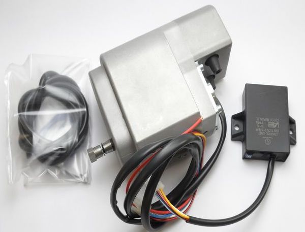
| The magdyno is sensible to blows during transport. We therefore double pack the material (box
inside box). Should the system have been despatched to you via a reseller
and arrive not packed like this, please inform us.
The charging system is only suitable for use with rechargable 12V lead-acid batteries with liquide electrolyte or sealed lead-acid batteries, AGM, Gel. It is not suitable for use with nickel-cadmium, nickel-metal-hydride, lithium-ion or any other types of recharchable or non rechargable batteries. | |
First of all, make sure that the unit is suitable for your application. You should consider the following
points:
|
|||||||||||||||||||||||||||||||
Please note that some characteristics of the unit differ from the original
magdyno:
|
|||||||||||||||||||||||||||||||
|
|
|||||||||||||||||||||||||||||||
 |
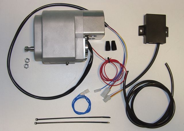
These parts are in the Lucas version pack:
|
||||||||||||||||||||||||||||||
|
|
|||||||||||||||||||||||||||||||
 |
These parts are in the Bosch version pack:
|
||||||||||||||||||||||||||||||
|
|
|||||||||||||||||||||||||||||||
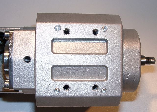 |
As we have unified Bosch und Lucas versions to some extent, you will find at the bottom of the unit the usual 4 holes for the small Bosch dowels and 4 holes threaded M8 to take the adapterplate needed for the Lucas version. Should you screw into the threaded holes for whatever reason something else than our lucas adapter plate with the screws we supply, make sure that screws do not touch the rotor inside (max screw depth from surface: 13mm) |
||||||||||||||||||||||||||||||
|
|
|||||||||||||||||||||||||||||||
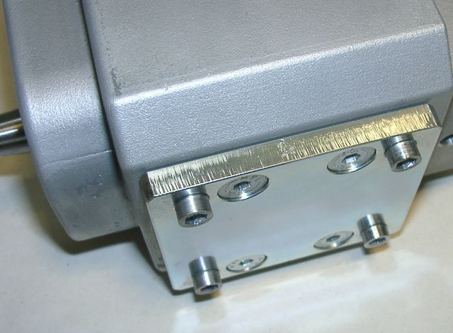 |
For Lucas applications the unit is fitted with a bottom adapter plate, bringing the shaft to the correct height and providing for the dowels. The dowels are screwed in and may therefore be taken out (hex key) or replaced by screws (watch out for length!) if required for the particular installation. |
||||||||||||||||||||||||||||||
|
|
|||||||||||||||||||||||||||||||
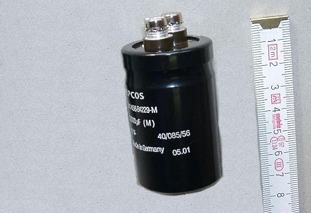 |
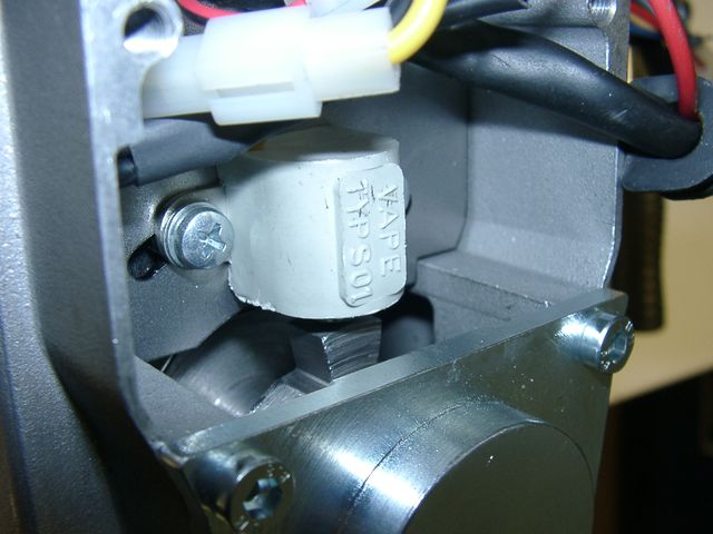
Not included, but necessary if you operate without a battery, is a smoothing capacitor. It must be installed in place of the battery and connected as if it were the battery. The capacitor has 2 screw-on terminals. One of them is marked with plus (+) and must be connected to plus (+). The other terminal (-) is connected to ground (negative). The red positive (+) wire of the magdyno must be connected to both the positive (+) terminal of the capacitor and to input terminal (pin 30) of the main switch, if fitted. |
||||||||||||||||||||||||||||||
|
|
|||||||||||||||||||||||||||||||
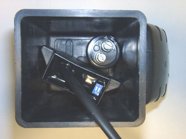 |
Recommended, for operating without a battery, but not included in the magdyno set is an * empty battery housing (similar in appearance to original Bosch) to contain both advance unit and capacitor. |
||||||||||||||||||||||||||||||
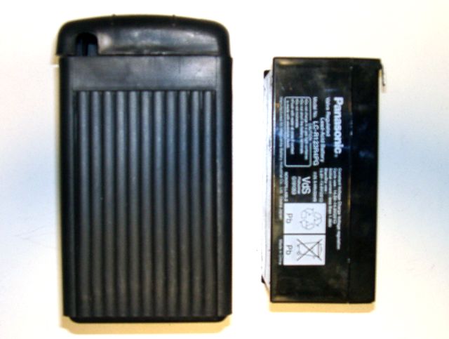 |
This empty housing may also be used to house a modern 12V sealed acid battery while maintaining the appearance of the original. |
||||||||||||||||||||||||||||||
|
|
|||||||||||||||||||||||||||||||
|
Preparation of Installation |
|||||||||||||||||||||||||||||||
|
|
||||||||||||||||||||||||||||||
|
|
|||||||||||||||||||||||||||||||
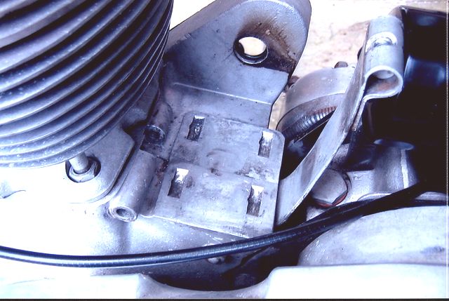
| The new magdyno is fastened to the motorcycle in the same way as the original magdyno had been fitted. | |||||||||||||||||||||||||||||||
|
|
|||||||||||||||||||||||||||||||
|
This adjustment of mesh is usually effected by placing shims between the unit and mounting platform. A worn idler may exhibit the same slow speed clatter even though the mesh is correct. For more detail on that see safety and operating information further down. |
|||||||||||||||||||||||||||||||
|
|
|||||||||||||||||||||||||||||||
| Observe that the taper of the rotor shaft is 1:5 and threaded for M8x1. Do not use sprockets on it with a different taper. This will damage the taper and may cause the sprocket to slip on the shaft. | |||||||||||||||||||||||||||||||
|
|
|||||||||||||||||||||||||||||||
 |
During assembly, pay attention to the small switches on the advance unit. There are 2 blue switches which select different advance curves. | ||||||||||||||||||||||||||||||
| For settings and curves of units
with serial numbers starting with 0806 and 1506
see here.
Other (later units have settings as described below). |
|||||||||||||||||||||||||||||||
|
|
|||||||||||||||||||||||||||||||

|
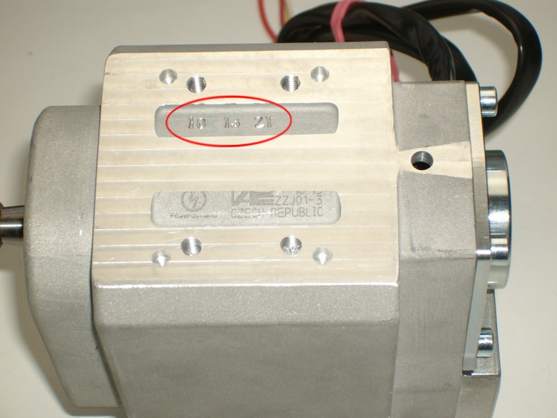
In the table below 1 means switch is set to ON 0 means it is set opposite, that is to OFF this example here is 1-0 |
||||||||||||||||||||||||||||||
Those curves have been introduced as it had been noticed that some machines with worn yet serviceable engines had difficulty in maintaining a regular idle speed of 1,000rpm or below. It was therefore necessary to introduce an A&R module with the advance threshold lifted to 1,250rpm to allow idle speeds to be increased to 1,250 rpm or below. At the same time it was advantageous to modify all settings to give a greater spread of options. |
|||||||||||||||||||||||||||||||
|
|
|||||||||||||||||||||||||||||||
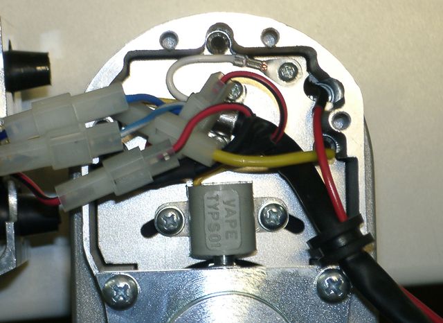
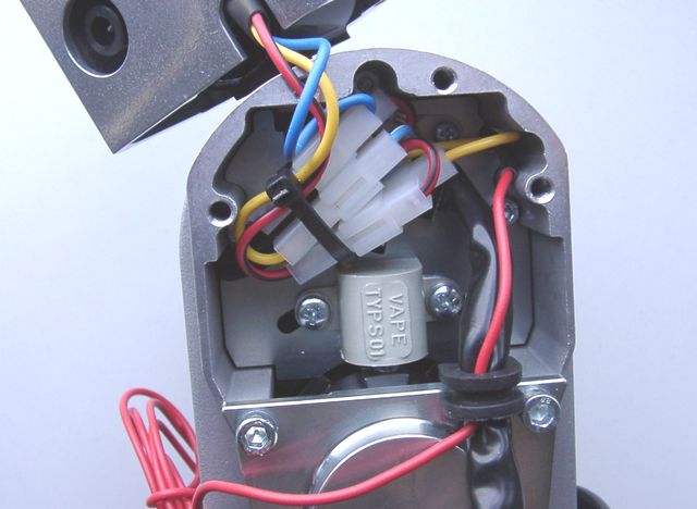
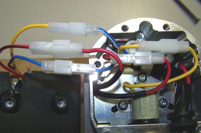
| The magdyno and its external advance unit are connected by a pre-assembled 4-terminal plug. | |||||||||||||||||||||||||||||||
|
If you have to replace it or there are cables out of the
plug, you must take care that all cables are connected correctly (see
left).
If the blue cable is connected to ground, the ignition is off. For a first test of the system you are advised to leave the blue wire open (unconnected). This will reduce the scope of possible errors. |
||||||||||||||||||||||||||||||
|
|
|||||||||||||||||||||||||||||||
|
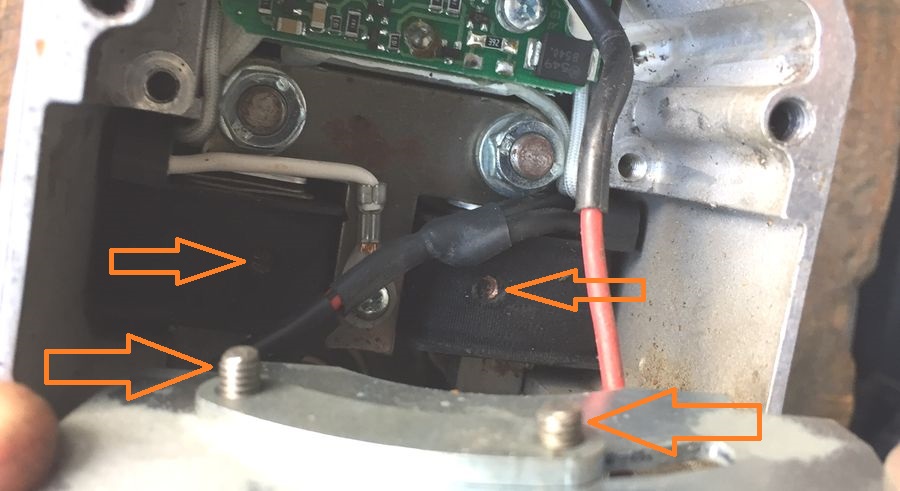
For ignition adjustment you must: |
|||||||||||||||||||||||||||||||
 |
Remove the 4 countersunk screws from the front upper cover. (Not the 4 lower hex head screws!) |
||||||||||||||||||||||||||||||
|
|
|||||||||||||||||||||||||||||||
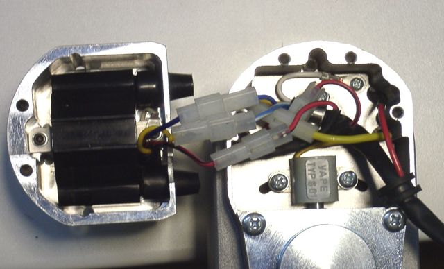
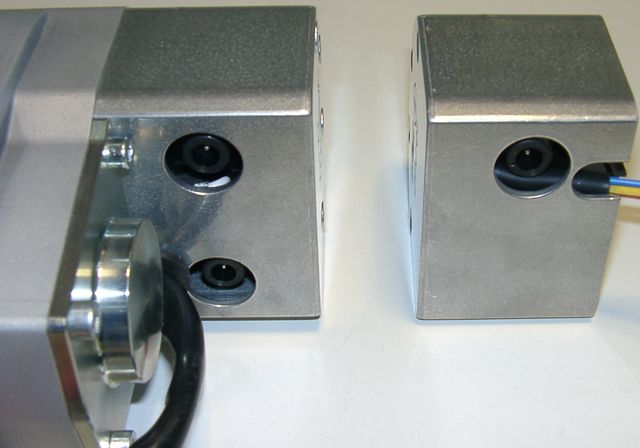
in the unit there are 2 further connectors: |
Pull off the cover (cap) carefully. Attention, not too far! The ignition coil is fastened with cables and plugs connected to the inside of the
unit.
|
||||||||||||||||||||||||||||||
|
|
|||||||||||||||||||||||||||||||
 |
You will see the grey sensor, and beneath it the rotor with its 1 or 2 trigger noses. The point of ignition is determined by the position of the trigger noses relative to the sensor. |
||||||||||||||||||||||||||||||
|
|
|||||||||||||||||||||||||||||||
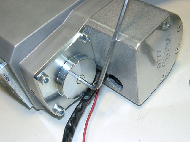 |
To facilitate turning the shaft, there is a hex screw in the end of the rotor shaft with an accessible
head.
You may insert a 3mm allen key to turn and hold it. |
||||||||||||||||||||||||||||||
|
|
|||||||||||||||||||||||||||||||
|
Setting timing during
installation
This is the point where most problems happen, so please read carefully and try to understand the logic of the process. |
|||||||||||||||||||||||||||||||
| 1. Prepare the new unit by setting it into position for full advance. | |||||||||||||||||||||||||||||||
| The following drawing shows where the sensor and rotor are in relation to each other when the spark actually occurs under conditions of maximal advance (that is normal driving speed). | |||||||||||||||||||||||||||||||
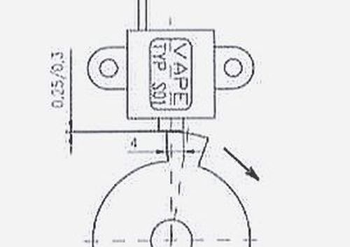 |
Position at full advance The position of full advance is reached (for clockwise turning units) when the left edge of the trigger has passed the sensor core by about 1/3 of its width (4mm). Turning clockwise means as seen from the front of the shaft (as shown here)! |
||||||||||||||||||||||||||||||
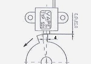 |
For counter-clockwise turning units (seen from this position) the same applies in reverse. The system is designed to work in either direction | .
||||||||||||||||||||||||||||||
|
|
|||||||||||||||||||||||||||||||
| 2. Prepare your engine by setting the crankshaft into the position that is normally reached at full advance (riding position). For most motorcycles using a magdyno this is typically around 38° to 40° (crankshaft) before TDC single spark advance and 32° to 34° twin spark. | |||||||||||||||||||||||||||||||
|
|
|||||||||||||||||||||||||||||||
| 3. With both, unit and engine in the described position the mag pinion or cog should be gently tapped onto taper and secured to 14 ft lbs with nut provided. Re-check timing in case of slippage. | |||||||||||||||||||||||||||||||
|
|
|||||||||||||||||||||||||||||||
 |
A perfectly accurate adjustment may be difficult (often prevented by the length of the timing chain links). Furthermore, positioning the rotor precisely in specified positions can be tricky as well (because of the strong magnets pulling it away). We have therefore provided a means to adjust the sensor position by shifting it laterally. |
||||||||||||||||||||||||||||||
|
|
|||||||||||||||||||||||||||||||
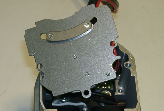 |
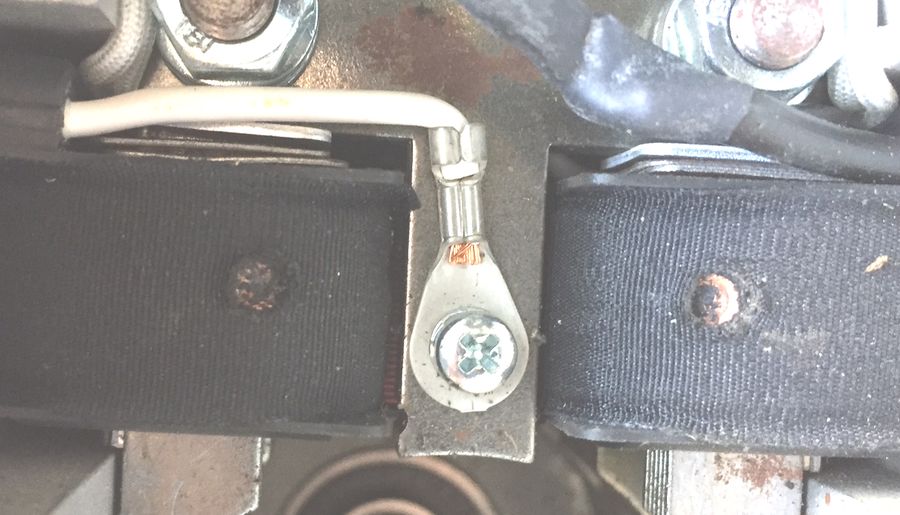
But attention: Loosen the holding screws only slightly - otherwise the back plate behind may fall inside the unit (attracted by the magnets) and damage the system, if you start it. Don't forget to tighten the screws after the adjustment!! Please check these screws for tightness even if you did not adjust the sensor position initially. |
||||||||||||||||||||||||||||||
|
|
|||||||||||||||||||||||||||||||
 |
NEVER change the screws holding the sensor
|
||||||||||||||||||||||||||||||
 |
|||||||||||||||||||||||||||||||
|
|
|||||||||||||||||||||||||||||||
 |
Whenever you have opened the ignition coil housing, you must be careful to ensure that all wires there are well secured and can not accidentally become entangled in the rotor. Use a cable tie to fasten them well up. Attention: Before starting fit a new plug and open the gap to 0.6mm/25thou. |
||||||||||||||||||||||||||||||
|
|
|||||||||||||||||||||||||||||||
|
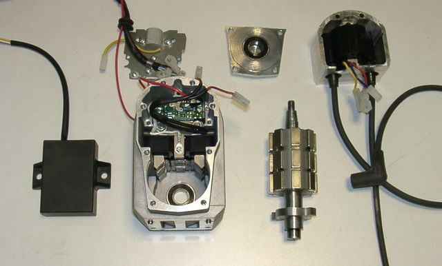
There is no reason to open the unit (except the cover for adjusting the sensor and checking screws and
cables)!! There are no other serviceable components inside. Unscrewing the rotor mounting plate could lead to severe damage and will void the warranty. If you suspect a defect in the system, you must return it to Powerdynamo for inspection and (if needed) repair. If you must know how it looks inside - here is a photo! (Click pictures to enlarge them!) |
||||||||||||||||||||||||||||||
|
|
|||||||||||||||||||||||||||||||
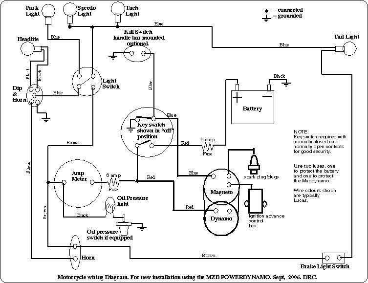
| Wiring will depend very much on what motorcycle you are using the magdyno for. There are however a few generally valid points. Below a general wiring diagram of a typical (British) vintage motorcycle with the new unit. You may enlarge this diagram by clicking onto it. | |||||||||||||||||||||||||||||||
|
|
||||||||||||||||||||||||||||||
|
|
|||||||||||||||||||||||||||||||
 |
The single cylinder version differs from the twin cylinder
(or twin spark) version only by the ignition coil and its cover.
Both have the same rotor with 2 noses and hence produce a wasted (harmless) spark on the exhaust stroke. If there is a twin ignition coil fitted, it always fires both plugs at the same time. |
||||||||||||||||||||||||||||||
|
|
|||||||||||||||||||||||||||||||
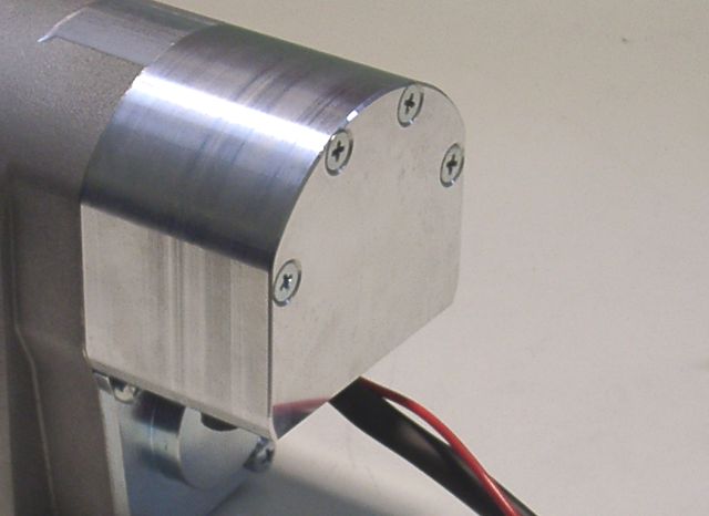
| During operation the unit will warm up
noticeably, especially at the front and the bottom. This temperature may
(with motorcycle not moving) climb up to 85°C (you should be careful when touching the hot
unit). This heat will not damage the electronics and is actually not produced by the electronics or near them. The heat comes from the
aluminium. Similar to a microwave oven, the strong magnetic field causes the alloy particles to rub against each
other, heating themselves up.
This is normal behaviour of the unit, there is no need to worry. |
|||||||||||||||||||||||||||||||
|
|
|||||||||||||||||||||||||||||||
| You will not be able to turn the shaft by hand. You must place a sprocket on the shaft
(or use the allen key in the front opening). When turning the shaft you will notice the resistance of the
magnets. That too is normal. Energy does not come from nothing. The high output of the unit requires a strong magnetic field created by very powerful high technology ceramic magnets.
Having mentioned the internal resistance, there is no need for worry that your engine cannot pull it, or will suffer a loss of power. Quite the contrary, you should notice improved engine performance. You may ease starting by switching the lights on only after the engine is running on its own. The lights consume a lot of energy and bring more load to bear on the magnets. That is a suggestion only, if needed. The engine will start with lights switched on before starting as well. |
|||||||||||||||||||||||||||||||
|
|
|||||||||||||||||||||||||||||||
|
You will find a unique unit idendity number on the bottom side of the magdyno unit. |
||||||||||||||||||||||||||||||
|
|
|||||||||||||||||||||||||||||||

|
You may check timing with a stroboscope. For this the engine has to be
running however.
Precise ways of doing that vary from motorcycle to motorcycle. You cannot check timing with a simple timing light bulb as used in points based applications. |
||||||||||||||||||||||||||||||
|
|
|||||||||||||||||||||||||||||||
|
|
Important safety and operating information |
|
# |
Safety first! Please observe the general health and safety regulations motor vehicle repair (MVR) as well as the safety information and obligations indicated by the manufacturer of your motorcycle. |
|
# |
Ignition systems generate high tension! With our material right up to 40.000 Volts! This may, if handled carelessly, not only be painful, but outrightly dangerous. Please do keep a safe distance to the electrode of your spark plug and open high tension cables. Should you need to test spark firing, hold the spark plug socket securely with some well insulating material and push it firmly to solid ground of the engine block to earth the output. |
|
# |
After installation, please check tightness of all screws. If parts get loose during run, there will be inevitably damage to the material. We pre-assemble screws only loosely. |
|
# |
Give the newly installed system a chance to work, before you start
to check and test values, or what is worse is to apply changes to
customize the firing point before running the system. Our parts have been checked before delivery to you. You will not be able to check much anyway. At any rate do refrain from measuring the electronic components (such as ignition coil, regulator and advance unit). You risk severe damage to the inner electronics there. You will not get any tangible results from the operation anyway. Bear in mind that also your carburettor and your spark plugs and spark plug sockets might be the reason for malfunction. The general experience with our systems is that the carburettor will have to be re-adjusted to lower settings. Should the system not start after assembly, first disconnect the blue cut-off wire directly at the ignition coil (or in some cases advance unit) to eliminate any mistake in the cut-off circuitry. Check ground connections carefully and, to be on the safe side and for testing, put an additional ground wire from the regulator directly to the engine block. |
|
# |
The spark of classical, points based ignition systems has with about 10,000 Volts with little energy and looks therefore yellow and fat (hence it's visible). The spark from our system is a high energy spark with up to 40,000 Volts and therefore very sharp (needle thin focused) in form and blue in colour, which makes it not so well visible. Furthermore you get spark only at kickstart operated speeds and not by pushing the kicklever down slow with your hand (as you might get on classic systems). |
|
# |
Systems using a twin outlet ignition coils have a few percularities. Please observe that during tests on one side, the other has either to be connected to an fitted spark plug or securely earthed. Otherwise there will be no spark on either side. |
|
# |
Never do electric arc welding on the bike without completely disconnecting all parts containing semiconductors (ignition coil, regulator, advance). Never use copper putty on spark plugs. |
|
# |
Electronics are very sensitive to wrong polarity. After work on the system, do check correct polarity of the battery and the regulator. Wrong polarity creates short circuits and will destroy the regulator, the ignition coil and the advance unit. As a rule, wiring will always be colour to colour. Instances, where colour differs between wires are expressly mentioned in our instructions. |
|
# |
Do not use spark plug sockets with a resistance of more than 5kOhm. Better use 1 or 2kOhm ones. Bear in mind that spark plug sockets do age and thereby increase their internal resistance. Should an engine start up only when cold, a defectice spark plug socket and/or spark plug is very probably the cause. In case of problems check high tension cables too. Never use carbon fibre HT-cables. |
|
# |
Should the motorcycle not be in use for some longer period, please disconnect the battery (so existing) to prevent current bleeding through the diodes of the regulator. Though, even a disconnected battery will empty itself after a while. |
|
# |
Please do observe these remarks, but at the same
time, don't be afraid of the installation process. Remember, before you,
that thousands of
other customers have successfully installed the system. Enjoy driving your bike with its new electric heart! |
|
|