Powerdynamo regresa el encendido
y la luz
a su moto clásica
![]()
![]()
![]()
![]()
![]()
![]()
![]()
![]()
|
|
Powerdynamo regresa el encendido |
|
|||
|
|
|
|
|
||
|
|
|||||
|
ˇApesadumbrado! |
versión 15.11.2010 |
|
|
Por favor lea primero las instrucciones completamente antes de empezar con la instalación o la modificación de las piezas. Tenga en cuenta las llamadas de atención en la página de informaciones para el sistema. |
| Si no tenga conocimientos técnicos para la instalación, entonces por favor deje realizarla de una persona cualificada o de un taller técnico correspondiente. Una instalación inadecuada causa dańo tanto en el nuevo sistema como en la motocicleta. | |
| Antes de pedir el sistema, por favor comprueba mediante la lista de paquetes (o bien la foto
"piezas en volumen de entrega") si la herramienta recomendada de nosotros para
extraer el rotor (extractor) está contenida en el volumen de
entrega. En caso negativo por lo mejor pídala también directamente.
ˇEn caso de dańo al rotor por usar otros herramientas y medios (inadecuados), el derecho de garantía
prescribe! Cuando un rotor está sentado demasiado bajo (por cualquier causa), toca y destruye la unidad de estator que está debajo. |
|
|
|
Si tiene acceso a Internet, vea esta documentación en línea. Puede ampliar los imagenes por cliquear sobre ellos y entonces recibe más
informaciones. Lista del sistema en: http://www.powerdynamo.biz |
|
|
El rotor es muy sensible a efectos de golpes (por ejemplo mientras el transporte). |
| Compruebe en cada caso antes de la instalación de la pieza el estado fijo de los magnéticos por intentar apartarlos con los dedos al
lado. Después de efectos de golpes, algunos de los magnéticos pegados podrían haberse soltados y podrían estar fijándose solamente por su poder magnético que resultaría en dańos graves en el dispositivo mientras el funcionamiento. Al mismo tiempo, por favor comruebe los magnéticos del rotor por cuerpos extrańos (por ejemplo tornillos u otros objetos metállicos). |
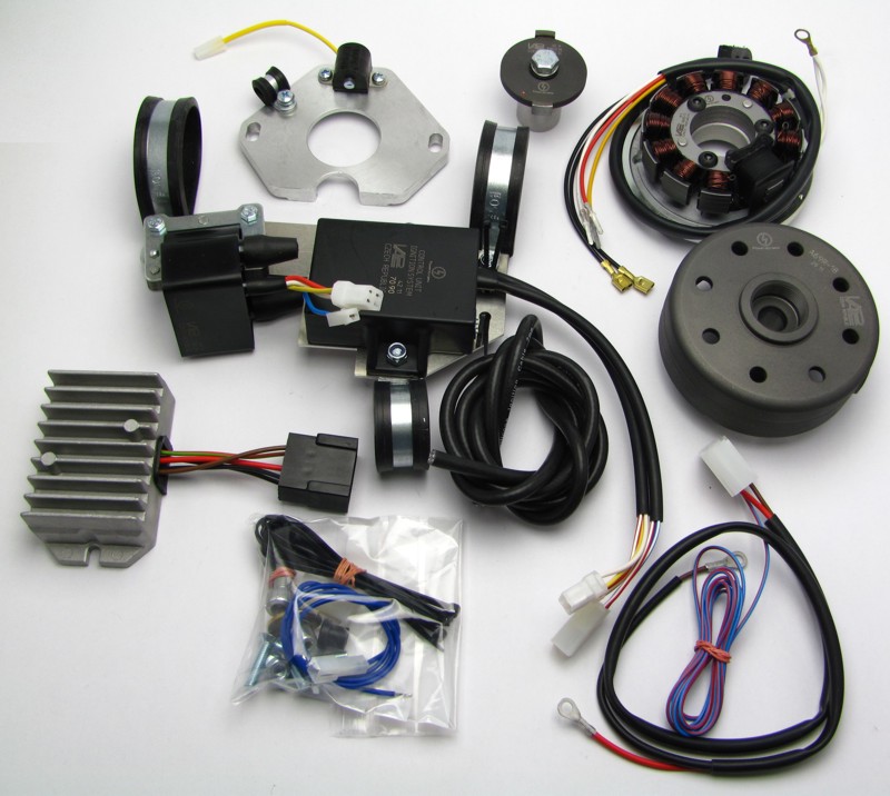 |
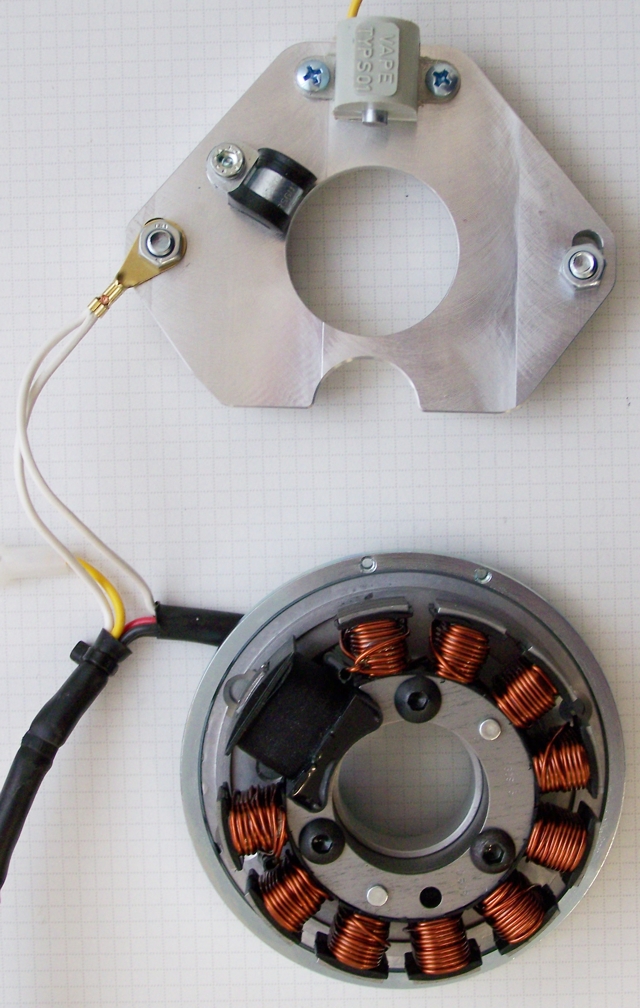
Estas partes las debe haber recibido:
|
| Please note that the stator coil is only
loosely fixed to the plate as you will have to lift it off a little for
assembly. Further note that the sensor is only loosely fixed, as you will
have to set it to correct gap.
The supplied mounting plate for the new ignition coil and advance unit and the attached clamps do not fit on any BMW frame. It must be modified or replaced in individual cases. |
|
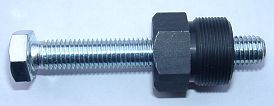 |
Para retirar el nuevo rotor necesita un extractor M27x1.25 (Número de partes: 99
99 799 00 -No
en el alcance de la fuente!-).
ATENCIÓN: ˇAl usar un extractor de garras se sueltan los imanes en el rotor! |
|
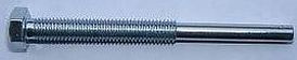
To disengage your old rotor, you will need a puller screw M8x90 (Número de partes: 70 80 899 90 -No en el alcance de la fuente!-). |
|
|
|
| Notes on wiring: Experience shows that over time nearly every motorcycle experiences changes to it's wiring. Additionally, most wires may have lost their original colours. For your reference we provide the original wiring diagrams of BMW 51/3 to 67 and R50, R60 on our website. | |
|
|
|
| Make sure your motorcycle rests securely, preferably on an elevated work bench and that you have good access
to the front of the engine. You will have to turn the front wheel
from time to time for better access.
Disconnect your battery and take it out of the motorcycle. Note that you will install a 12 volts system, so you will either need a 12 volt battery or you use the option of driving without. For driving without battery, please observe our information on driving without battery. You will still have to replace all lightbulbs to 12 volt ones. The horn may stay at 6 volts. Drain your petrol tank into a safe canister. Make sure you do not spill petrol. Refrain from smoking. Disconnect the connecting tube under the petrol (gas) tank and take the tank off. Put it into a safe place for the duration of the works. |
|
|
|
|
 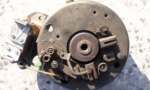 |
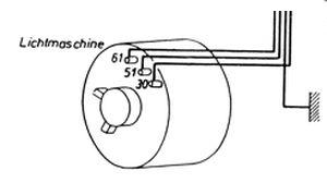
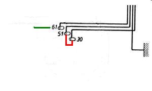
Unscrew the generator cover and take it off. Disconnect the wires from the old
generator, regulator and magneto. At the generator there should typically be:
|
|
|
|
|
Use a hex key (allan wrench) 5mm and remove the two screws retaining the
field of the generator to the engine casing. Remove the field. You might
need to gently bump its side with a rubber hammer to disengage it. Use
a hex key 6mm and remove the screw that retains the advance unit and the
magnetic rotor on the nose of the camshaft. To do that, you will have to
hold the generators rotor with your hand using a piece of cloth to avoid
injury. Take the centrifugal advance unit off.
Now remove the 2 nuts (spanner 10) which hold the magnet unit and take the part off the engine casing. Use again the hex key 6mm and remove the screw that retains the rotor on the nose of the crankshaft. In place of the now removed holder screw install the BMW rotor puller and screw it in till the rotor pops off (again, you will have to hold the rotor with your hand, and you might well have to use a little force on the puller). Lastly, pop the magnetic rotor off the camshaft, using the same puller and the same method already used for the rotor of the generator. |
|
|
|
| Rewire as follows: | |
|
|
Integration between the original general electric system (lighting, horn etc.) and the new system is at the battery (or should you drive without at the wires normally running to the battery). |
|
|
|
|
|
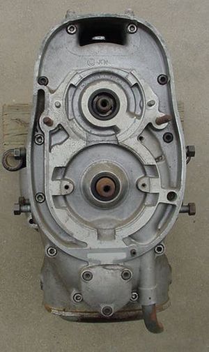
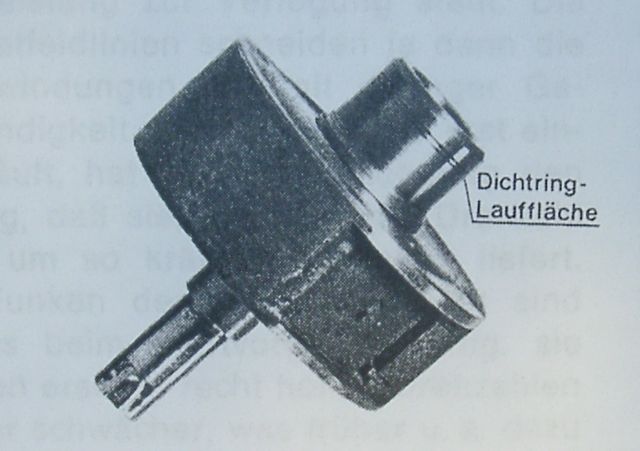
Check the diameter of the sealing stud on the original magneto rotor. |
|
Should you find 28mm there, you will have to replace the existing oil seal 28x40x7 by one with 25x40x7. Otherwise you will not seal the oil there. |
|
|
|
|
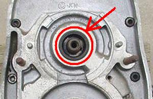
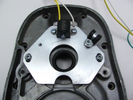
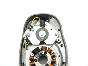
Place the holder plate for the new
pick-up module onto the engine. Into the place the old magneto unit
had been and screw it down.
Place the screws into the middle of the long (adjustment) holes to enable timing adjustment. |
|
|
|
|
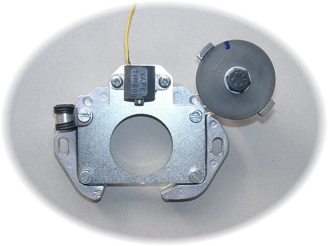
The new stator unit is pre-assembled so that you can recognize its
structure more easily. To install it, it has to be partially disassembled
however.
Take care not to damage the paint insulation of the coils.
Unscrew the new stator coil from its base plate (the 3 hex screws) and lift it a little away from it so that you can access the mounting holes in the base plate. Now put the base plate consisting of the steel ring and the base plate (aluminium) onto the engine block and screw it down with the 2 screws M6 provided. |
|
|
|
 |
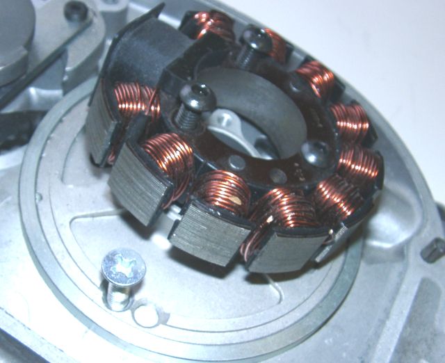
Now put the stator coil back into its position on the plate, taking care not the
damage the wires. Make sure that the inner opening of the stator unit slots evenly over the
elevated fixing rim of the base plate - otherwise the coil will sit loopsided
and will touch the rotor, damaging it.
Screw the coil down with the 3 hex screws M6x30 and tighten. The thick black coil will now show into an about 11 o'clock direction. The wire will either run as shown here upwards through the opening between the base for the dynamo and the base for the magneto or it can be usehere out sideways as shown on some of the following pictures. The long cable has to be lead out through the top opening into the rear of the engine. |
|
|
|
 |
Screw the white ground cables coming from the stator unit down to the holding plate of the pick-up. |
|
|
|
|
Put the rotor onto the crank and screw it down with the provided screw M8x40. Do not forget to place the washer there. To disangage the rotor again, use a puller M27x1.25, never a claw puller or hammer blows! |
|
|
|
 |
En el cable del estator se encuentra una boquilla de paso.
Presione éste dentro de la apertura de cables y corte con cuidado el material que sobresale. |
|
|
|
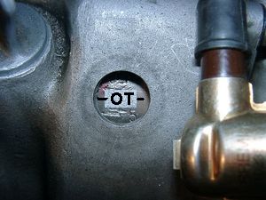 |
You will now have to bring the crank into top dead center position (TDC).
Make sure that you first take both spark plugs out to get rid of the
compression. Start moving the crank with the kick lever and finetune by hand
using the new rotor.
You have a TDC ("OT") marking on the flywheel which can be seen through the inspection hole on the bike's lefthand side. Make sure to use the OT marking (top dead center) and not one of the other (advance) markings. |
|
|
|
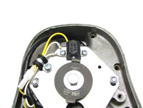
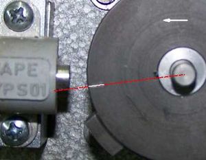 |
Once you found the crank's top dead center position hold it and place the cam with the rotor disc (you have done away with the screw M5 for transportation use) onto the camshafts nose - so that its marking will allign with the left edge of the sensor's core. In this position screw it securely down with the special screw provided. With that you have set ignition timing to standard values. You may vary this setting by shifting the whole ignition module in its long holes (as you did before with the original magneto). |
|
|
|
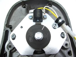 |
Turn the black rotor on the crankshaft again by hand to bring the middle of
either of the two perimeter elevations (noses) of the new magunits
rotordisc to stand at the sensor and check that the gap between the sensor
pin and the highest point of the rotor disc's elevation has the required 0,4mm
gap. If not, loosen the sensor screws, adjust and retighten carefully.
Even if by chance the gap was correct, fasten the screws! They are loose at time of delivery. |
|
|
|
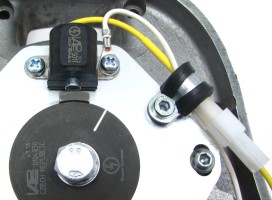 |
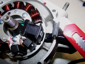
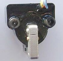
Connect the yellow wire from the pickup with the yellow wire from the cable
on the generator and fix the wires with the provided small clamp to prevent
it from interfering with the rotor.
Now work on the engine is finished. Place the spark plugs back. |
|
|
|
| The following is a proposal which you may alter if you so wish (in the case of the 51/3 and the 67 you have to do differently as the tank tunnel is not wide enough for the rather bulby ignition coil. For those bikes the system 70 81 999 0XX is the better option): | |
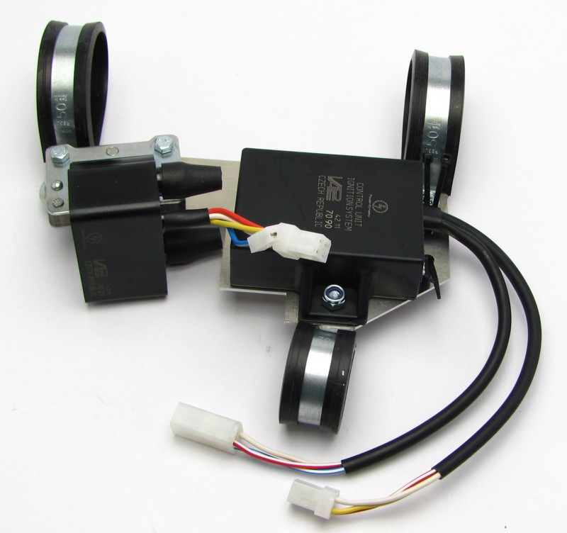 |
The new electronic ignition coil and the advance unit are pre-mounted on a holder plate which itself will be fitted with 3 clamps to the frame under the petrol (gas) tank. The supplied mounting plate for the new ignition coil and advance unit and the attached clamps do not fit on any BMW frame. It must be modified or replaced in individual cases. |
|
|
|
  There is no difference between the BMW curves in the 2 unit versions. |
Have a look at the advance unit (the black box). You will
notice on the side the wires come out small switches. They are used to
activate different advance curves inside the bow.
The BMW curve is activated when all of them (older systems had 2, newer have 4) are set towards the printed numbers, away from ON (that is to OFF). |
|
|
|
|
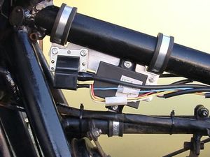
First, take the loosely pre-assembled 3 clamps off. Than screw the new high tension (HT) cables into the outlets of the new ignition coil (this would be more difficult once the coil is on the bike) and unfasten the strapping of the original wiring harness to get some needed flexibility. Put the 2 larger clamps with the black rubber insets onto the upper frame tube (the one directly under the tank). Make sure to put the closed, straight side of the clamps to the right side side, with the hole facing downwards. The first clamp has to sit about 15mm away from the steering head and the second about 170mm from the head. As the clamps get widened by putting them on, use a pair of pliers to close them again. Now put the 3rd, smaller clamp onto the frame tube below the 2 clamps between horn and engine mount. Again with the closed, straight part of the clamp to the righthand side. |
| Put the holder plate (with the pre-mounted electronic parts) from the left side to the 3 clamps. Do not put the holder plate between the clamps, but to their left sides. Attach the plate to the clamps, using the supplied screws. For the upper front clamp the screw goes in from the left and for the upper rear clamp from the right. The screw for the bottom clamp will be inserted too from the right side.. Arrange the plate between the 2 frame tubes so that none of it could - under the influence of the bikes vibrations - scratch the frame. It should sit vertically a little outside centre to the right. Fasten the screws of the complete holder assembly. | |
|
|
|
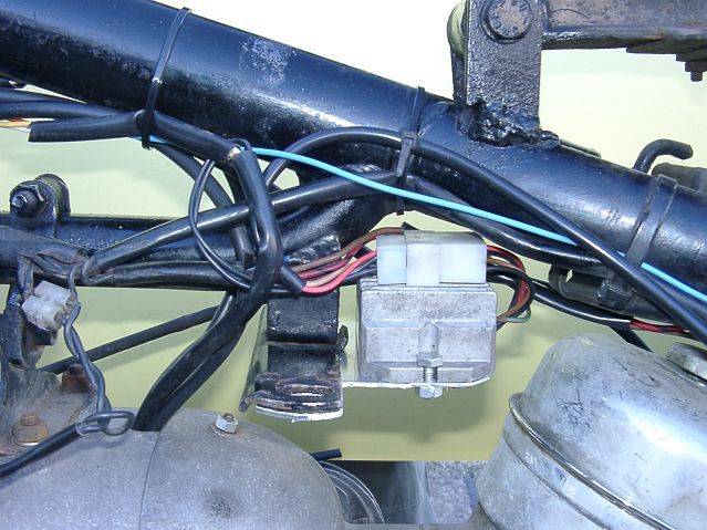 |
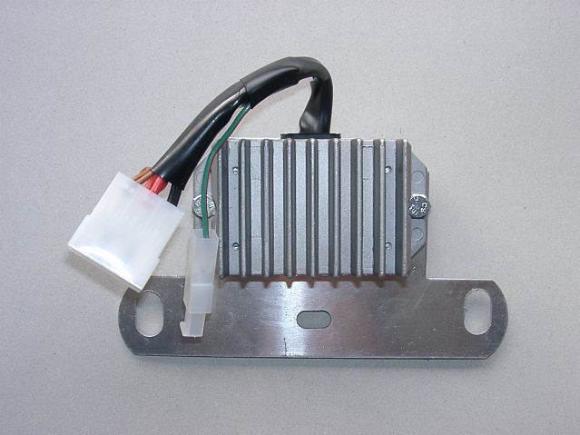
The new regulator/rectifier could be fitted under the rear holder for the petrol tank.
(On this proposal the customer has used a selfmade
unit plate.) For this, unscrew the nut (spanner 13) securing your BMW's tank holder and put your new
regulator plate (with the regulator on it) underneath. The
regulators cooling fins will face upwards. Put the nut back, do not forget to
put the washer back.
You may fit the regulator/rectifier in any other way. |
|
|
|
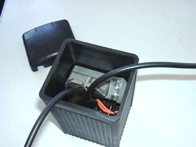 |
If you opt to drive without battery, something technically possible with this system, you may place the regulator and the advance unit into an empty battery casing. |
|
|
|
|
Empalme los cables como indicado en el diagrama de circuito 92xk12 entonces: |
|||||
|
* |
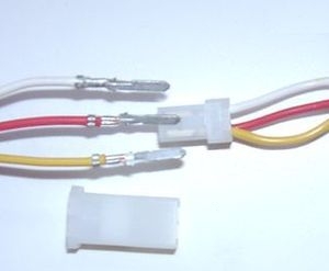
Para hacerlo más fácil el paso del cable por las aberturas estrechas o sea para hacerlo posible, el enchufe del cable que lleva hasta la nueva bobina de encendido desde la nueva dinamo todavía no está puesto en las vías de contacto al final del cable. Usted debería fijar el enchufe sólo cuando el cable está llevado definitivamente por la abertura del motor. Para esto... | ||||
|
|
… tome el enchufe feminino de la unidad anticipada de la ignición con los cables de colores rojo y
blanco.
Ponga el estuche de enchufe 4 aflojado (que está incluido en el paquete) en este enchufe e introduzca los cables aflojados (rojo, amarillo y blanco) de la dinamo con las vías de contacto en el enchufe por atrás. Atienda a que las vías de contacto encajan en la carcasa de enchufe. Con esto hay que atender estrictamente a la posición correcta del cable en el enchufe:
|
||||
|
Si quiere (o tiene que) sacar los cables otra vez de la carcasa de enchufe, lo mejor es de utilizar un sujetapapeles desdoblado y empuje con esto los garfios de las vías de contacto a un lado, para que los enchufes se aflojen. |
|||||
| * |
El segundo enchufe de la unidad anticipada de la ignición hay que conectar con el enchufe de la bobina de encendido. También esto sólo va en una única posición . En esto va ... |
|
|||
| * |
OJO! En ningún caso debería acomodar el / los cable(s) de encendido y el / los cable(s) de la unidad anticipada de la ignición juntos en la misma envoltura o en otra manera por algún tiempo paralelo uno a otro. Esto acaba en una retroalimentación y con esto en averías del encendido, tal vez también en la destrucción de la unidad anticipada de la ignición. |
||||
|
* |
|
El nuevo moderador/rectificador tiene un enchufe compacto con 6 posibilidades de introducir de cuales sólo uno está libre (antes de noviembre de 2007 eran dos). Para el moderador está incluido (a partir de los envíos de noviembre de 2007) en el paquete un equivalente adecuado en cuál hay que introducir los siguientes cables que tienen que encajar allí. | |||
|
* |
Los dos cables negros de la nueva dinamo ... |
... hay que conectar con los bornes 1/4 del nuevo rectificador (desde allí entran entonces también cables negros en el regulador). En esto da igual cuál de los cables va con cuál de los dos bornes (1/4), porque aquí hay corriente alterna. |
|||
| * | El nuevo cable marrón con el ojete de forma de un aro a un lado ... |
... conecta el borne 3 del regulador/rectificador (desde allí también entra un cable marrón en el regulador) con el polo negativo de la batería o bien con masa sólida. ˇOjo! ˇNo debería poner los polos al revés! |
|||
| * |
El nuevo cable rojo con el ojete de forma de un aro a un lado ... |
... conecta el borne 5 del regulador/rectificador (desde allí también entra un cable rojo en el regulador) con el polo positivo de la batería o bien con el borne de la caja de fusible a la cual que llegaba el cable de corriente de la dinamo vieja (motos alemanes: borne 51). |
|||
| Compruebe que haya fusible 16 A entre la batería y la red de bordo. Si haya un fusible viejo, más fuerte (por el dispositivo de 6 Voltio antiguo) al contacto, por favor reemplazelo. | |||||
|
* |
El cable verde/rojo del nuevo regulador al borne 6 ... Indicación: |
... es para la conexión del control de cargar. Aquí hay que conectar (si esté disponible) la lámpara de contról. Claro que esto sólo funciona si está disponible una batería. Si la lámpara de contról está conectada (a pesar de todo) sin batería, la lámpara va a dar luz medio oscura mientras el motor está arrancado, aunque esté producido electricidad. En pocas palabras: Sin batería el contacto se queda libre. También cuando no haya una lámpara. |
|||
|
La navigación de la lámpara de control de cargar es una función adicional
- controlado por transistor - del regulador/rectificador. También si esta
sería defectuosa, la función verdadera de la pieza está garantizada. Esto es muy fácil para comprobar: Deje el motor arranquado, encienda las luces y desconecte la batería. Cuando la luz queda encendida, el regulador está bien. |
|||||
| * |
Queda el cable azúl (de vez en cuando también azúl/blanco) de la bobina de encendido - el cable de apagar.
Ojo: |
ˇConectandolo con masa, el encendido se apaga!
Esta variante de conexión utilizamos con vehículos que ya tenían originalmente un encendido de imán (rueda de polo) y que apagaban con un cortocircuito contra la masa. |
|||
| * |
El cable de alta tensión (cable de encendido)...
Por favor, no utiliza el "Nology Superkabel"/"Nology Supercable" ("hot wire"). Ellos producen averías con sistemas de Powerdynamo y pueden producir dańo de la electrónica. |
… lo atornille en la bobina de encendido y pone la tapa de goma sobre ello. Claro que esto va mucho mejor si lo haga antes de instalar la bobina en el vehículo. Por favor sólo utilize el cable de encendido incluido en el paquete y no uno viejo, indefinido. | |||
|
Hagase un favor e invite a vuestra moto a tener unas nuevas bujías y unos enchufes de bujía (de preferencia con
resistencia de 0 a 2 kOhmio). ˇMuchas averías se deben a "pareciendo
buenos" cables, bujías o enchufes (entre ellos absolutamente nuevos)!
No utiliza bujías con una resistencia de desaveriar al interior. Por ejemplo NGK ofrece unas bujías con el códico "R" ("R" por resistor). |
|||||
| * |
|
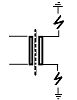
En nuestras bobinas de encendido dobles llegan ambas salidas primero a las bujías
y sólo por ellos a la masa.
La resistencia típica entre las dos salidas totaliza 6,2kOhmio. Ambos canales siempre calientan al mismo momento (que es - por cierto - el caso normal en muchos sistemas de encendido y que es sin escrúpulos). Pero las chispas tienen a ambos lados una fase desplazada por 180 grados cada uno, que debería tener en cuenta en mediciones con el estroboscopio. |
|||
| El encendido sólo funciona correctamente si ambas bujías están conectadas con la bobina. Entonces no puede quitar una sólo para comprobar. Porque cada salida coje masa por la bujía de la otra salida. Si quiere comprobar verdaderamente sólo un lado, debería poner la otra salida de la bobina sobre masa. Luego la conexión funciona como la de una bobina con sólo una salida (mire más arriba). Si el curso de electricidad de un lado está interrumpido, o no funciona nada o el sistema coje masa del punto más cercano. Muchas veces esto tiene de consecuencia unos fuegos artificiales alrededor de la bobina de encendido. Los que necesitan verdaderamente dos salidas separadas tienen que utilizar 2 bobinas solteras. | |||||
|
* |
Para terminar - antes del primer arranque - por favor compruebe con toda calma todas las fijaciones y todos los cableados. No olvida de cambiar todas bombillas de 6 voltio por las de 12 voltio. El claxon de 6 voltio puede quedarse. Si el sistema no funciona directamente, por favor consulte nuestra página de busqueda de errores. Para primer paso separe el cable azúl entre el relé y la bobina de encendido (extraer el contacto). En el sector de apagar se esconde la mayoridad de los errores. |
||||
| * |
IMPORTANTE: Por favor, tenga en cuenta que el tapón de dinamo del cigüeńal se ha hecho más corto por embalarlo en una regeneración del cigüeńal casual (anterior). Por eso el rotor está más abajo y se puede producir un contacto entre el rotor (los remaches son el punto más abajo) y la bobina de estator. El resultado es un estator destruido y por eso una interrupción de
encendido. ˇPara más informaciones mire (en línea) aquí! |
||||
|
Importantes llamadas de atención de seguridad y de funcionamiento: |
|
|
# |
Haga caso a las llamadas de atención de seguridad e imposiciones reglamentarias del fabricante del vehículo y del oficio de vehículos. |
|
# |
ˇCentrales de cebado producen alta tensión! ˇCon nuestras bobinas de ignición hasta 40.000 voltio! ˇEsto no sólo puede hacer mucho dańo si lo utiliza siendo incauto, sino también puede causar problemas para el corazón! Por eso preserve siempre la distancia de seguridad al electrodo y a cables de alta tensión abiertos y en el test siempre pulse con fuerza el macho de enchufe de la bujía de encendido (enchufes de bujía) con un objeto aislador a la masa para desviar seguramente el voltaje. |
|
# |
Después de la instalación, por favor compruebe el estado fijo de los tornillos de apoyo del estator y (si existente) del senor. Si las piezas se aflojan, se surgirá la destrucción. ˇSólo apretamos los tornillos en el preénsamblaje sueltamente! |
|
# |
Dele primero por lo menos una oportunidad al dispositivo recién instalado de encenderse, antes de empezar de medir y de comprobar todo si funciona verdaderamente. O peor: hacer modificaciones directamente sin haber encendido la instalación. Todas nuestras piezas están comprobados antes de la entrega. Además no van a tener suerte medirlas. Por favor, deje la medida de las piezas electrónicas (entre ellas la bobina de encendido con excepción de su salida de alta tensión). ˇAriesga la destrucción y no van a llegar a resultados usables! Piense en esto: también pueden ser el carburador y sobre todo los soportes de bujía y las bujías (por lástima también las completamente nuevas) si el motor no va directamente (regularmente, después de la instalación de Lima, también sus regulaciones deberían ser cambiadas). Si el dispositivo no va directamente, sobre todo compruebe las conexiones de masa, pone por lo menos para el test un nuevo cable de toma de tierra de nuestro regulador directamente al motor. |
|
# |
Si tiene un dispositivo con bobina de encendido doble, por favor tenga en cuenta algunas particularidades de esta bobina. El encendido sólo funciona corectamente si ambas bujías están conectadas con la bobina. Entonces no puede quitar una bujía sólo para testar. Es porque cada salida carga masa por la bujía de la otra salida. Si quiere testar seguramente sólo un lado hay que poner la otra salida de bobina sobre masa. |
|
# |
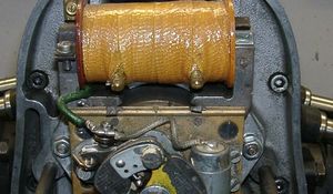
La chispa de centrales de interrupción clásicas tiene con 10.000 voltios sólo una energía pequeńa y es por eso amarilla y gorda. La chispa de nuestras centrales es una chispa de alta energía con hasta 40.000 voltios y es por eso muy concentrado y azúl, que le hace menos buen visto. Además esta chispa está producida sólo con un número de revoluciones pedaleado con el pedal de arranque. Sólo estirar el pedal de arranque con la mano no produce una chispa. |
|
# |
Nunca hacer la soldadura de arco eléctrico en la bicicleta sin desconectar completamente todas las partes que contengan semiconductores (bobina de encendido, regulador de antelación) estator y el rotor no es necesario que se deban tomar fuera. |
|
# |
La electrónica es sensible al polo falso. Compruebe siempre después de una intervención al sistema la conexión correcta de la batería y el cableado correcto. Polos falsos y cortocircuitos destruyen el regulador y la bobina de encendido. Normalmente hay que conectar en el cableado siempre color con color. Excepciones están mencionadas explícito en la instrucción. |
|
# |
Atienda a no romper los imanes mientras la instalación del rotor. Evite la influencia mecánica y directa al rotor. Para el transporte de la Lima nunca ponga el estator en el rotor, atienda a las indicaciones para el envío (embalaje). |
|
# |
No utilice enchufes de bujía con una resistencia a más de 5 kOhmios. Recuerde que enchufes de bujía envejiecen y que intensifican con eso su resistencia. Si un motor sólo arranca en estado frío con gran seguridad la razón es un enchufe de bujía defecto. No utilice cables llamados aumentando el encendido (por ejemplo Nology). |
|
# |
Engrase el rotor un poco por fuera, sino va a corroerse rápidamente en el entorno agresivo (que no hace dańo pero parece muy feo). |
|
# |
No utilice nunca un para extraer el rotor un extraido de forma de garras o un martillo. Con estos se podrían aflojar los imanes. Siempre sólo un extraido de tornillo solo M27x1.25 (mire las instrucciones de instalación). |
|
# |
Si vuestro vehículo no está utilizado por un poco más tiempo, debería desconectar la batería (si existente) para evitar una descarga lenta por los diodos del rectificador de corriente. Pero también va a darse cuenta de una descarga de la batería después de algún tiempo aunque habrála desconectado, eso es normal. |
|
# |
Por favor presta atención a estas indicaciones pero tampoco dejese confundir. Antes de usted, miles de clientes ya han instalado nuestros dispositivos con éxito. ˇMucho éxito y que se divierte conduciendo! |