Powerdynamo regresa el encendido
y la luz
a su moto clásica
![]()
![]()
![]()
![]()
![]()
![]()
![]()
![]()
|
|
Powerdynamo regresa el encendido |
|
|||
|
|
|
|
|
||
|
|
|||||
|
ˇApesadumbrado! |
versión 25.10.2010 |
|
|
Por favor lea primero las instrucciones completamente antes de empezar con la instalación o la modificación de las piezas. Tenga en cuenta las llamadas de atención en la página de informaciones para el sistema. |
| Si no tenga conocimientos técnicos para la instalación, entonces por favor deje realizarla de una persona cualificada o de un taller técnico correspondiente. Una instalación inadecuada causa dańo tanto en el nuevo sistema como en la motocicleta. | |
| Antes de pedir el sistema, por favor comprueba mediante la lista de paquetes (o bien la foto
"piezas en volumen de entrega") si la herramienta recomendada de nosotros para
extraer el rotor (extractor) está contenida en el volumen de
entrega. En caso negativo por lo mejor pídala también directamente.
ˇEn caso de dańo al rotor por usar otros herramientas y medios (inadecuados), el derecho de garantía
prescribe! Cuando un rotor está sentado demasiado bajo (por cualquier causa), toca y destruye la unidad de estator que está debajo. |
|
|
|
Si tiene acceso a Internet, vea esta documentación en línea. Puede ampliar los imagenes por cliquear sobre ellos y entonces recibe más
informaciones. Lista del sistema en: http://www.powerdynamo.biz |
|
|
El rotor es muy sensible a efectos de golpes (por ejemplo mientras el transporte). |
| Compruebe en cada caso antes de la instalación de la pieza el estado fijo de los magnéticos por intentar apartarlos con los dedos al
lado. Después de efectos de golpes, algunos de los magnéticos pegados podrían haberse soltados y podrían estar fijándose solamente por su poder magnético que resultaría en dańos graves en el dispositivo mientras el funcionamiento. Al mismo tiempo, por favor comruebe los magnéticos del rotor por cuerpos extrańos (por ejemplo tornillos u otros objetos metállicos). |
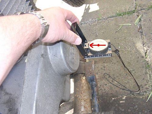 |
If you have not already done before
ordering the system, please check the direction
of the magnetic field of your ETZ generator, to find out whether you
need, system S1 or S3.
To do that, you have to start the motorcycle - something that hopefully is still possible at that stage, switch on the headlight and run the engine at about half speed (stationary!). Now hold a compass (any simple type will do) against the right side of the engine (the dynamo cover may stay in place). If the marked end of the needle points towards the engine, the S1 is OK, if the needle points however away from the engine, you need S3. |
|
|
|
 |
S3 is really the exeption and should only
be needed in motorcycles with rotors made after 1991. After that date,
unfortunately no attention had been paid to the winding direction. As a
result we get magnetic fields inversed by 180°. This interfers with our systems and leads to a rapid destruction of the ignition coil. Quite often the engine does not start and run well with the wrong polarity. |
|
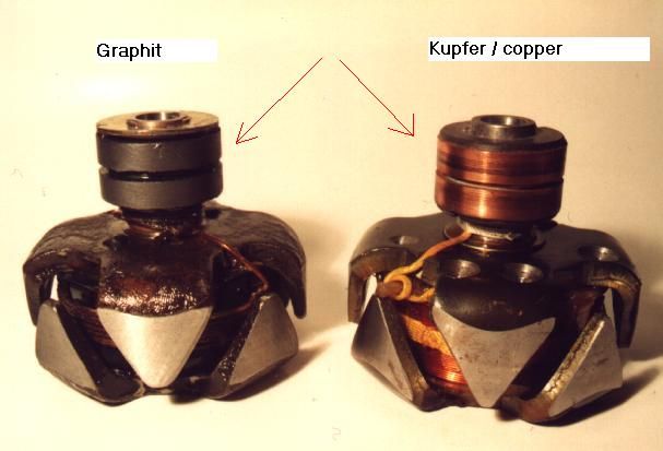
Rule of thumb if you can not check
the field: If the rotor rings are made of graphite, S1 is correct, if they are made of copper, you have to employ the compass method, there is no other way of telling with those rotors!! |
|
|
|
|
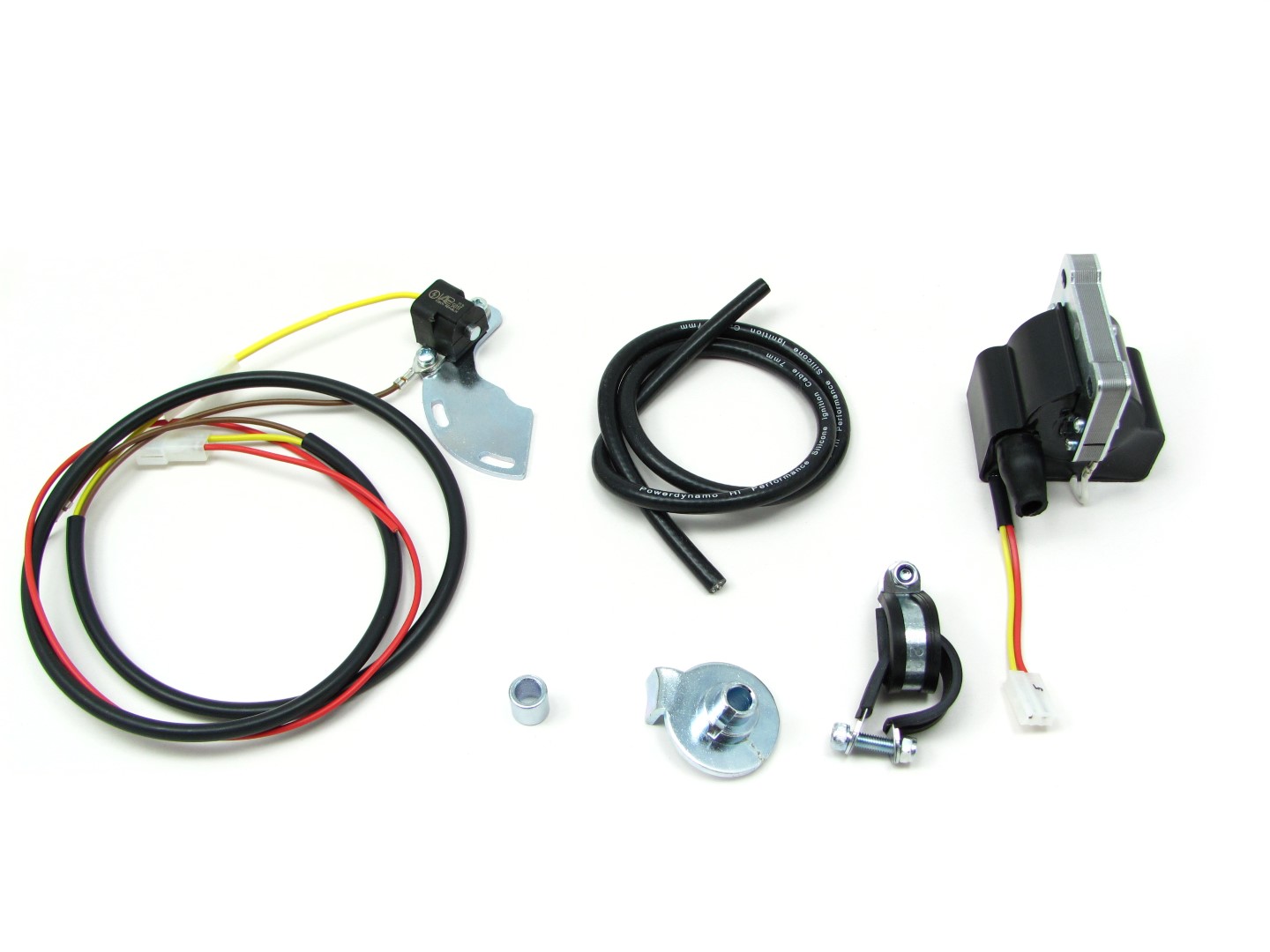 |
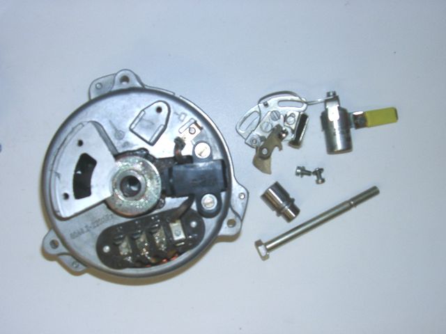
Estas partes las debe haber recibido!
Note, that the sensor module is only loosely fixed at the base plate, as it has to be adjusted by you. Disconnect the battery and better take it off the bike for the time of work to prevent shortcircuits. |
|
|
|
| Disconnect the green wire from the points plate or whatever wires you might have at any electronic trigger there. Do not remove that wire however, you will make use of it again. | |
|
Unscrew the rotor bolt and take this long screw M7 off. Rotor ans stator
housing however remain in place.
Take the cam (or whatever rotor arrangement for any electronic ignition you might have there) off. Take the points plate and the condenser off. From the parts taken off, you will only need the long screw M7. |
|
|
|
|
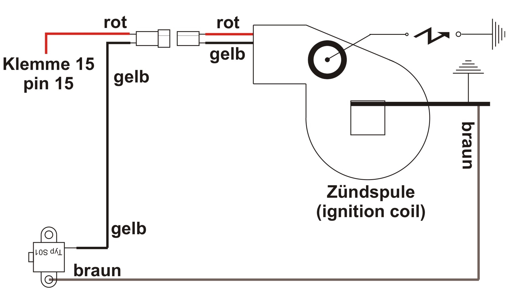
Take the original ignition coil (and so you have any ignition boxes) off
the bike. Memorize the wires that did run to your ignition coil. With the standard points based ignition those should be a green wire at pin 1 of the coil and 2 red/black wires joint in one ring-terminal at pin 15. Do not cut the 2 wires originally sitting at pin 15. Your stop/tail light would not work anymore. |
|
|
|
|
|
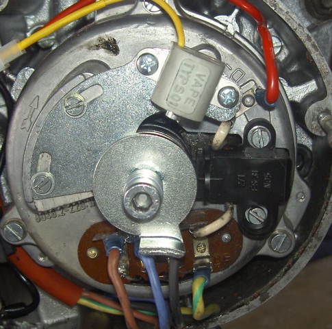
Now place the new holder plate with the sensor onto the generator, same
place points had been sitting. Fasten with the screws used before for the
points.
Place the new rotor disc onto the rotor (in place of the cam). Put the supplied 6 washers 7.2mm on the long screw M7 and screw it back into the rotor. (The 6 washers are needed as the screw is now too long, but getting a long M7 is a headache!) |
|
|
|
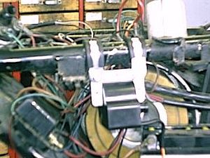 |
Fasten the new ignition coil on the rear right tube,
directly in front of where the old coil had been fixed to the frame of the ETZ.
Use the 2 supplied clamps for that.
There are physical differences in the frames for the different ETZ versions. On some, you will manage only to install one clamp. In that case, use as additional holding material a cable fixer. Do not forget to put the ground wire to the coils metal frame. Without this ignition will not work. |
|
|
|
|
|
The red wire of the new coil will be conected to the red/black wire, that did run before to pin 15 of the old coil (arriving from the main switch). The old green wire is not been needed anymore. |
| NOTE: Any (even the briefest) confusion between the yellow and red wire of the coil will destroy it on the spot. The same is true for any mixup in connecting the battery. Never connect the batterie's plus to the frame. | |
|
|
|
|
Now, all is fixed and you may set timing.
Note, that you cannot check with a simple light, as you did before on
points. Never use this light check on electronic ignitions, you kill
the electronics. He, who is not happy with the below described
method should get himself a stroboscope to check.
Take the spark plug out and bring the piston into top dead center position (TDC). Turn the crank shaft anticlockwise, so that the pistons falls by nearly 3mm (2.75 to be precise). There are special tools to help you, but a simple pencil and good eyesight will equally do. |
|
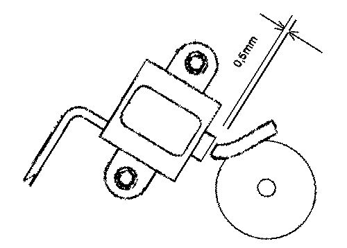 Position of rotor finger at moment of ignition. |
Hold that piston position and shift
the sensor holder plate in such a way that the top left corner of the
finger of the new rotor aligns with the pin of the sensor. In that
position fasten the sensor plate.
Check the gap between the sensor and
the finger of the rotor. This has to be 0.4-0.6mm. To change that, loosen the 2 sensor screws and shift it. Tighten the screws
afterwards carefully! Tighten, even if by chance the gap was correct
from start. |
|
|
|
|
Check everything over again, especially
wiring. Put the battery in, connect it and start. The system should work. |
|
|
|
|
|
Importantes llamadas de atención de seguridad y de funcionamiento: |
|
|
# |
Haga caso a las llamadas de atención de seguridad e imposiciones reglamentarias del fabricante del vehículo y del oficio de vehículos. |
|
# |
ˇCentrales de cebado producen alta tensión! ˇCon nuestras bobinas de ignición hasta 40.000 voltio! ˇEsto no sólo puede hacer mucho dańo si lo utiliza siendo incauto, sino también puede causar problemas para el corazón! Por eso preserve siempre la distancia de seguridad al electrodo y a cables de alta tensión abiertos y en el test siempre pulse con fuerza el macho de enchufe de la bujía de encendido (enchufes de bujía) con un objeto aislador a la masa para desviar seguramente el voltaje. |
|
# |
Después de la instalación, por favor compruebe el estado fijo de los tornillos de apoyo del estator y (si existente) del senor. Si las piezas se aflojan, se surgirá la destrucción. ˇSólo apretamos los tornillos en el preénsamblaje sueltamente! |
|
# |
Dele primero por lo menos una oportunidad al dispositivo recién instalado de encenderse, antes de empezar de medir y de comprobar todo si funciona verdaderamente. O peor: hacer modificaciones directamente sin haber encendido la instalación. Todas nuestras piezas están comprobados antes de la entrega. Además no van a tener suerte medirlas. Por favor, deje la medida de las piezas electrónicas (entre ellas la bobina de encendido con excepción de su salida de alta tensión). ˇAriesga la destrucción y no van a llegar a resultados usables! Piense en esto: también pueden ser el carburador y sobre todo los soportes de bujía y las bujías (por lástima también las completamente nuevas) si el motor no va directamente (regularmente, después de la instalación de Lima, también sus regulaciones deberían ser cambiadas). Si el dispositivo no va directamente, sobre todo compruebe las conexiones de masa, pone por lo menos para el test un nuevo cable de toma de tierra de nuestro regulador directamente al motor. |
|
# |
Si tiene un dispositivo con bobina de encendido doble, por favor tenga en cuenta algunas particularidades de esta bobina. El encendido sólo funciona corectamente si ambas bujías están conectadas con la bobina. Entonces no puede quitar una bujía sólo para testar. Es porque cada salida carga masa por la bujía de la otra salida. Si quiere testar seguramente sólo un lado hay que poner la otra salida de bobina sobre masa. |
|
# |
La chispa de centrales de interrupción clásicas tiene con 10.000 voltios sólo una energía pequeńa y es por eso amarilla y gorda. La chispa de nuestras centrales es una chispa de alta energía con hasta 40.000 voltios y es por eso muy concentrado y azúl, que le hace menos buen visto. Además esta chispa está producida sólo con un número de revoluciones pedaleado con el pedal de arranque. Sólo estirar el pedal de arranque con la mano no produce una chispa. |
|
# |
Nunca hacer la soldadura de arco eléctrico en la bicicleta sin desconectar completamente todas las partes que contengan semiconductores (bobina de encendido, regulador de antelación) estator y el rotor no es necesario que se deban tomar fuera. |
|
# |
La electrónica es sensible al polo falso. Compruebe siempre después de una intervención al sistema la conexión correcta de la batería y el cableado correcto. Polos falsos y cortocircuitos destruyen el regulador y la bobina de encendido. Normalmente hay que conectar en el cableado siempre color con color. Excepciones están mencionadas explícito en la instrucción. |
|
# |
Atienda a no romper los imanes mientras la instalación del rotor. Evite la influencia mecánica y directa al rotor. Para el transporte de la Lima nunca ponga el estator en el rotor, atienda a las indicaciones para el envío (embalaje). |
|
# |
No utilice enchufes de bujía con una resistencia a más de 5 kOhmios. Recuerde que enchufes de bujía envejiecen y que intensifican con eso su resistencia. Si un motor sólo arranca en estado frío con gran seguridad la razón es un enchufe de bujía defecto. No utilice cables llamados aumentando el encendido (por ejemplo Nology). |
|
# |
Engrase el rotor un poco por fuera, sino va a corroerse rápidamente en el entorno agresivo (que no hace dańo pero parece muy feo). |
|
# |
No utilice nunca un para extraer el rotor un extraido de forma de garras o un martillo. Con estos se podrían aflojar los imanes. Siempre sólo un extraido de tornillo solo M27x1.25 (mire las instrucciones de instalación). |
|
# |
Si vuestro vehículo no está utilizado por un poco más tiempo, debería desconectar la batería (si existente) para evitar una descarga lenta por los diodos del rectificador de corriente. Pero también va a darse cuenta de una descarga de la batería después de algún tiempo aunque habrála desconectado, eso es normal. |
|
# |
Por favor presta atención a estas indicaciones pero tampoco dejese confundir. Antes de usted, miles de clientes ya han instalado nuestros dispositivos con éxito. ˇMucho éxito y que se divierte conduciendo! |