Powerdynamo brings new ignition & light
to your
classic bike
|
|
Powerdynamo brings new ignition & light |
|
|
|
|
|
||
|---|---|---|---|
| Installation of parts at engine level in pictures | click on photos to enlarge them | |
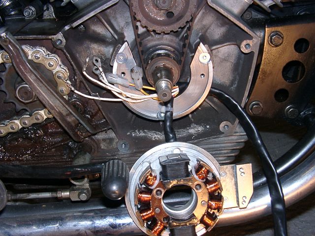 |
The open outer adapter plate ("Horseshoe") is
fastened to the engine with 3 countersunk screws M6. At that point the wire from the stator is put through there, but with the stator and the inner adapter plates still dangling loosely. |
|
 |
Now the inner adapter ring and the stator base (aluminium)
will be fixed to the outer adapter with 2 countersunk screws M5. One screw M3 from the upper pickup holder plate has to remain open for the moment as beneth is one fastening screw. The stator will still hang loosely at the wires. |
|
 |
The stator is now put onto ist base and fixed there with 2
screws M6. Addationally the 2 pickups will be fixed. To their lower fastening screw a white ground wire (each) is fixed. |
|
 |
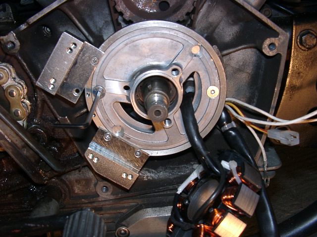
The harness to the stator gets secured by a wire binder to the engine casing to prevent it from interfering later with the rotor. Now the cable is led towards the wire exit at top left. | |
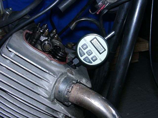 |
The piston of the front cylinder (cylinder 1) is brought into TDC position. It does not matter in what cycle the engine is. Important is that you get Top Dead Center. | |
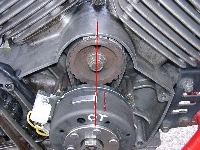 |
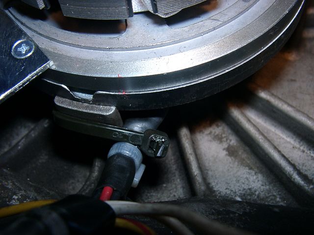
With the crank at TDC for the 1st cylinder the rotor is
put onto the shaft. This in such a way that the clockwise edge of the
rotor protrusion is vertically below the center of the camshaft. In most Morinis TDC is marked by a small hole on the camshaft wheel aligning with the middle of the housing (click picture to see that) |
|
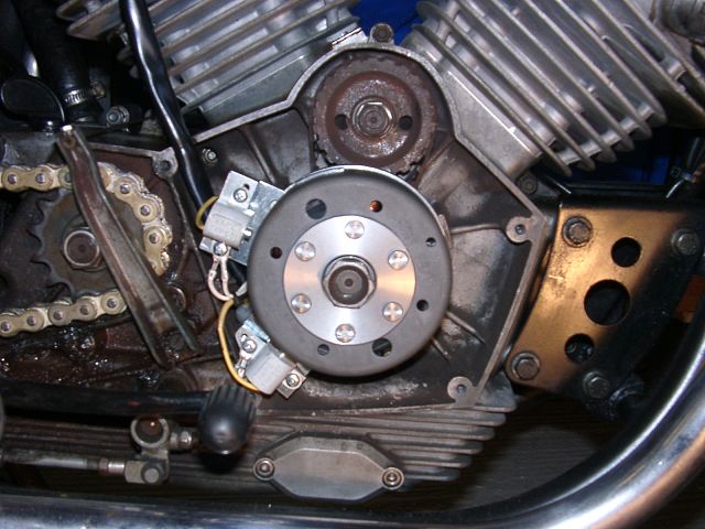 |
In that position the rotor is carefully screwed down with
the original nut. Now tidy the wires a little, if needed fix them additionally to make sure they do not get into the way of revolving parts. |
|
|
|
||
|
|