Powerdynamo brings new ignition & light
to your vintage motorcycl
![]()
![]()
![]()
![]()
|
Powerdynamo brings new ignition & light |
|||||
|
|
|||||
| Assembly instructions for System 70 78 999 00 |
Version 18.07.2008 |
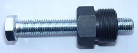 |
To pull the new rotor again, you need a puller M27x1,25 (part 99 99 799 00
-not provided-).
You have to pull the rotor for change the spark advance. Note: Never use a claw puller, a hammer or any other device, that will shake the magnets off. |
||||
|
|
|||||
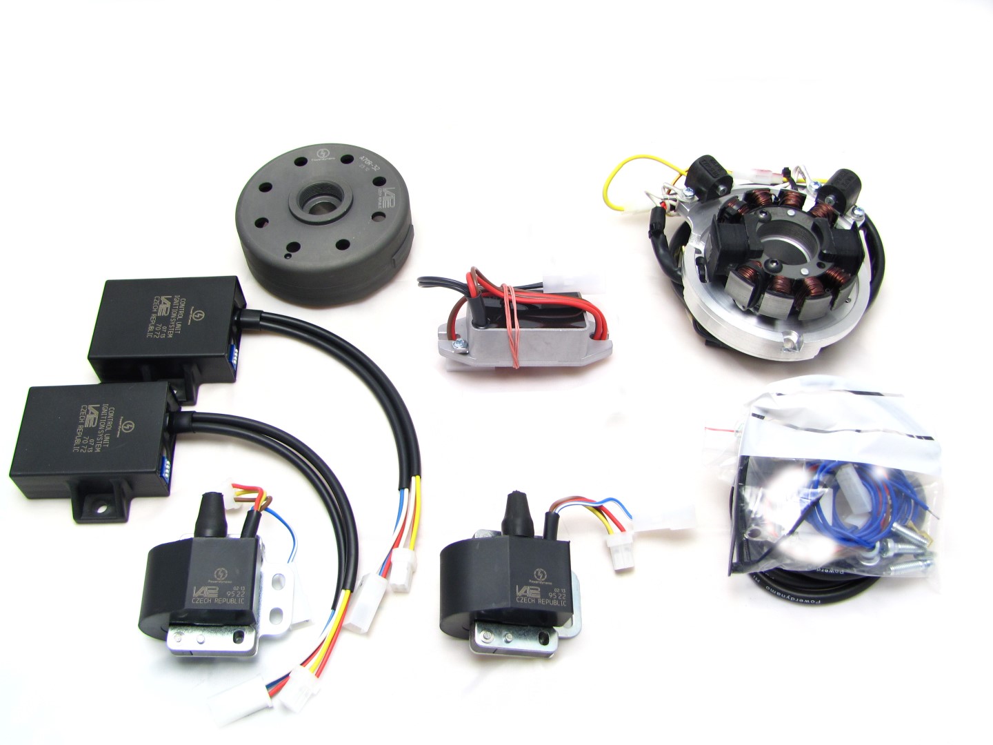 |
You should have received those parts!
Please pay attention: the sensors are not screwed tight on the ground plate, they have to be adjusted by yourself. |
||||
|
|
|||||
| Make sure your motorcycle rests securely,
preferably on an elevated work bench and that you have good access to the
dynamo side of the engine.
Disconnect your battery and take it out of the motorcycle. Note that you will install a 12 volts system, so you will either need a 12 volt battery or you use the option of driving without battery. If there are bullseye indicator at your bike, you have to installate a electrolyt capacitor (min. 20.000mF/16V) for smoothing the pulsing voltage instead of the battery. You will still have to replace all lightbulbs to 12 volt ones. The horn may stay at 6 volts. It might be that your local road traffic regulations demand the existence of a parking light facility (and hence battery). |
|||||
|
|
|||||
|
Take off the old dynamo, the two advance units and the regulator/rectifier.
Take the woodruff key from the crank. You will not need it any more. Please do not forget to do so, otherwise you will have trouble later on in the assembly. (Remark: This woodruff key does not actually hold your rotor on the shaft, this is done by the cone. It simply guides to the correct setting which will now be otherwise achieved.) Remove too the compression spring (the distance between new rotor's shaft and the drive wheel for the toothed belt amounts only 1mm). |
||||
|
|
|||||
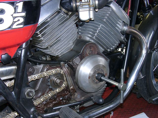
 |
You can see here (assembly
illustrated in pictures) how to installate the new dynamo.
One of the 3 countersunk screws M6x14 has to screwed down underneath the sensor plate. That's why you have to remove the left mounting screw M3 and lift the plate for get access to that screw. |
||||
|
|
|||||
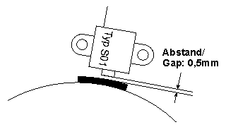 |
You have to turn the rotor, for getting the protrusion aligns with one of
the sensors (see left). For adjusting the sensors (0.4-0.5mm), loose the two
holding screws and shift it.
Now you have to do the same with the 2nd sensor. The cables for the 1st cylinder's sensor are yellow/red coloured and for the 2nd in yellow. Fasten the mounting screws for both sensors carefully. |
||||
|
|
|||||
|
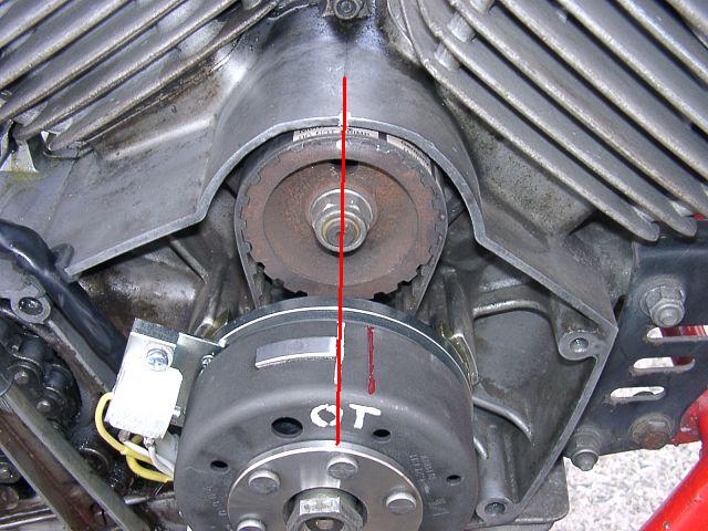
Now you have to bring the piston of the front cylinder (1) in TDC (Top Dead
Centre).
In this position put on the rotor in that way, that the right edge of the protrusion aligns to the centre of the cam shaft. The TDC position is at many Morini at the cam shaft marked with a little hole (cover mid edge). (Click on the photo!) |
||||
|
Screw down the original mounting nut for fasten the rotor in this position.
Arrange the sensor cables and fasten they by using a cable binder.
Therewith you have adjusted the ignition point alike the original system. If you think another setting would be better, you have to loose and pull-off the rotor. Then put it back on the shaft, distorted in the required angle. Theoretically should be adjusted every ignition point, but practically you would reach the motor's odds. The ignition point of the rear cylinder (2) is shifted against the front cylinder (1) about 72°. With that you have finished the works at he motor case. |
|||||
|
|
|||||
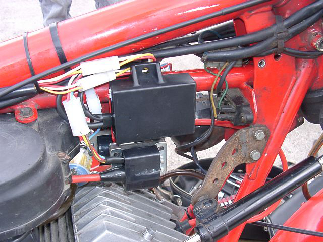 |
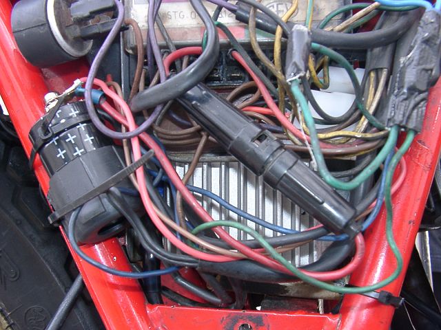
Fasten the both advance units (check at this time the setting of the switches - see below) and ignition coils (previously screw in the ht-cables) at an convenient place, maybe under the tank or the seat. | ||||
|
|||||
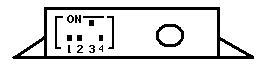
| The correct advance curve for the Morini is activated with switch 3 set to "ON" and switches 1, 2 and 4 set to "OFF". | |||||
|
|
|||||
|
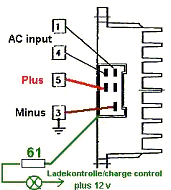
Fasten the electronic rectifier/regulator of your MZ-B-Tronics at a convenient place, maybe where the original were placed. The chassis is connected intern to minus. | ||||
|
|
|||||
|
|||||
|
The lighting circuit has no electrically connection to the ignition
circuit at all. The elctronical revolution counter won't be connected. |
|||||
|
|
|||||
|
|
It could be, you like to change the ignition after a first test run. Then you
have to:
|
||||
|
|
|||||
|
|