Powerdynamo brings new ignition & light
to your vintage motorcycle
![]()
![]()
|
|
Powerdynamo brings new ignition & light |
|
|||
|
|
|||||
|---|---|---|---|---|---|
| Inition timing wrong after engine repair (new or repaired crank) | |
|---|---|
|
This information may be used to check and set timing in all
Powerdynamo 2 stroke alternator-based ignition systems on cranks turning
clockwise. We have again and again customers who have problems with timing of systems using a woodruff key to fix rotor position but have wrongly assembled crankshafts which have the woodruff in the wrong place. Those problems, as others, may be easily solved as described below: |
|
|
|
|
|
Systems with external triggering (Sensor S01) For internally triggered systems see below |
|
|
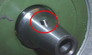
Pull the woodruff (or pin). No worry, your rotor will still hold on to the shaft |
|
|
|
| Have a look at the new rotor. You will find on its circumference one or two elevations. Those are trigger signs. DO they near the sensor core (the metal pin in it) ignition is triggered (on 2 strokes without advance control only) | |
|
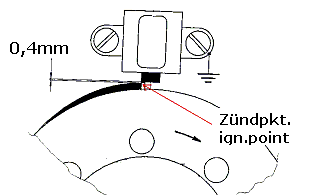
To set timing, you bring the piston into correct firing position (see your manual) and than set the rotor in such a way onto the shaft that the start of its elevation is just at the sensor pin (see sketch) both markings align. Check that the gap between sensor and rotor nose (elevation) is 0.3-0.4mm (if you have more engine has starting problems) Note: on systems with advance control this is different! See here |
|
|
|
|
Experience tells us that one problem never comes alone. Others might well
be lurking somewhere. So at this point please check that
|
|
|
|
| Systems with internal trigger | |
|
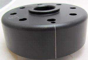
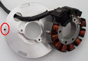
Have a look at the rotor (flywheel). On its circumference you will find a small lasered on line (older versions pressed in line). |
|
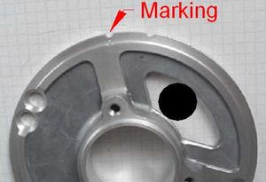
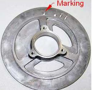
Have a look at the stator carrier plate (aluminium). There you will
find (depending on diameter) at the perimeter or further inside a few
small holes (or half holes). |
|
As mentioned on larger plates of this type the marking is a complete hole (not only a half one) and is situated further away from the perimeter. Note that the above shown markings are valid only for clockwise turning systems. |
|
On plates of other construction, as on anticlockwise turning systems we set a small dot or line on the plate (normally indicated in the corresponding instructions) For systems with advance control also see information here. |
|
|
|
|
At the moment ignition is triggered, both the rotor line and the shown
base marking align. To set timing, you bring the piston into correct firing position (see your manual) and than set the rotor in such a way onto the shaft that both markings align. |
|
|
|
| back to KB overview |
|
|