Powerdynamo bringt Ihrem Oldtimer Motorrad
wieder Zündung und
Licht
![]()
![]()
|
|
Powerdynamo bringt Ihrem Oldtimer Motorrad |
|
|||
|
|
|||||
| Assembly instructions for System 73 61 999 XXX | Version 22.03.2016 |
|
If you can install and time a stock ignition and
possess basic mechanical skills, you can install a Powerdynamo! |
|
| Powerdynamo can not monitor the compliance to those instructions, nor the conditions and methods of installation, operation, usage and maintenance of the system. Improper installation may result in damage to property and possibly even bodily injury. Therefore we assume no responsibility for loss, damage or cost which result from, or are in any way related to, incorrect installation, improper operation, or incorrect use and maintenance. We reserve the right to make changes to the product, technical data or assembly and operating instructions without prior notice. | |
|
|
Please read these
instructions fully and carefully before starting work on your motorcycle Please bear in mind that any modification of the material as well as own repair attempts which have not been agreed with Powerdynamo may result in a loss of warranty. Do not cut off wires. This leads to a loss of reverse polarity protection and often results in damage to electronics. Also, please take note of the information provided on the information page for this system. Check that what you have bought really corresponds to the motorcycle you have. Wrong ignition settings may damage your engine and even hurt you during kickstart (violent kickbacks). Be careful during the first test runs. If needed change settings to safer values (less advance). During assembly check carefully that the rotor (flywheel) does not touch the stator coils or anything else, which may happen due to various circumstances and lead to severe damage. |
| Designated use This system is designated to replace stock dynamo/alternator & ignition systems in vintage and classic motorcycles whose engine characteristics have not been modified aftermarket. This system is not a tuning system and it will not bring significant increases in engine output. It does however significantly enhance roadworthiness and comfort by offering better lighting, better function of side indicators and horn and, compared with the aging stock systems, increased reliability. As our system does not tamper with engine characteristics it does not increase emission of gaseous pollutants and noise. In most cases emission of pollutants should even be reduced due to better combustion. If used as designated the system therefore will not normally infringe the existing legal status of the motorcycle (this statement is valid for Germany, for other countries, please check locally against your road licensing regulations). This system is not suitable for use in competition events. If used other than the designated way, warranty will be voided and it might well be that you do not obtain the desired results or, worst you loose legal roadworthiness. The charging system is only suitable for use with rechargable 12V (6V systems 6V) lead-acid batteries with liquide electrolyte or sealed lead-acid batteries, AGM, Gel. It is not suitable for use with nickel-cadmium, nickel-metal-hydride, lithium-ion or any other types of recharchable or non rechargable batteries. This is a replacement system and not a copy of the stock material. The parts in this system therefore look different and might fit differently (notably ignition coil and regulator) requiring some adaptation by you. |
|
| During assembly imperatively start with assy of engine based parts to see that those really fit before you start fitting the external parts. In many cases customers assemble those first and thereby often modify them in breach of warranty which renders them unfit for renewed sale. Replacing old ignition systems is not a matter of taking something from a supermarket shelf as there have been very many types, versions and possibly unknown aftermarket modifications which harbour plenty of room for error. | |
| Our systems are NOT tested for use with third party electronic devices (such as GPS, mobile phones, LED lighting etc)and may cause damage to such parts. Possibly existing electronic tachometers will not work with the new system. Read our information for suitable solutions. Possibly existing safety switches and electronic valve controls are not supported. It might be that your motorcycle was originally equipped with an ignition that did limit top speed for legal reasons. The new system does not have such a facility, so check your legal situation beforehand. | |
| If you have no expertise for the installation have it done by an expert or at a specialist's workshop. Improper installation may damage the new system and your motorcycle, possibly even lead to bodily harm. | |
| Before you order a system, please check whether a puller
tool for the new rotor is included in the kit. If not,
better order it at the same time. You might want to order light bulbs,
fuse, horn,
flasher
unit etc. Never use anything other than the recommended puller tool to pull the new rotor again. Damage to the rotor as a result of use of other tools or methods is not covered by warranty. |
|
| The rotor is sensible to blows (including during transport). Before assembly, please always check for damage (on rotor without magnet plastification try to push the magnets aside with your fingers). After impact the glued in magnets might have broken loose, sticking to the rotor solely by magnetic force, so that one does not notice right away. During engine run the damage would be considerable. Before placing the rotor onto the engine, please make sure that its magnets have not collected any metal objects such as small screws, nuts and washers. That equally would lead to severe damage. | |
|
|
If you have access to the Internet, best view those instructions online. You get larger and better pictures by clicking onto them and possibly updated information. System list at http://www.powerdynamo.biz |
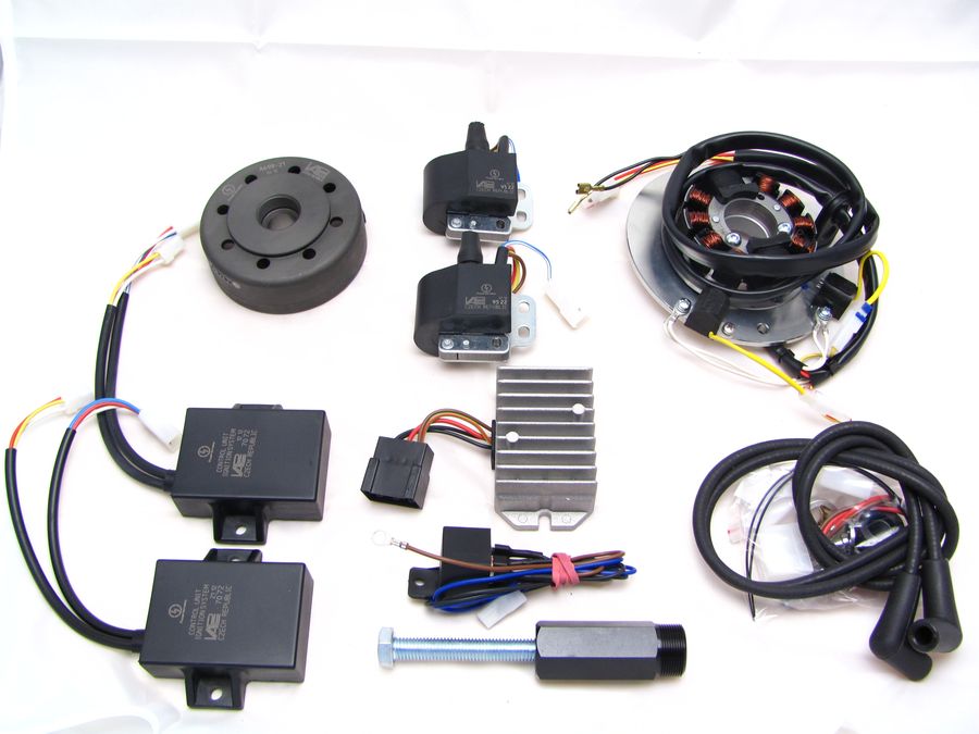 |
Diese Teile
sollten Sie erhalten haben:
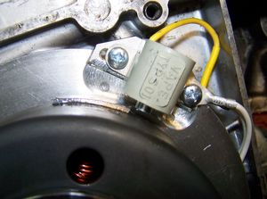
Note that the sensors (pickups) are only loosely screwed, because they have to be adjusted. Tighten these bolts to well after adjustment. |
||||
|
|
|||||
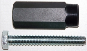 |
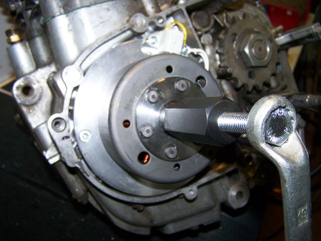
To pull the new rotor/flywheel off again please ONLY use the provided
puller M27x1.25 (order no. 71 69 999 99). NOTE: When using a hammer or a claw extractor the magnets in the rotor may be damaged! |
||||
|
|
|||||
|
|||||
|
|
|||||
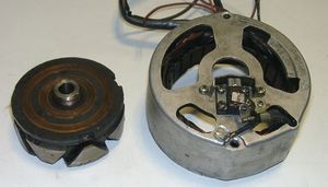 |
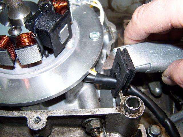
Remove the cables
from the old alternator.
Unscrew the old stator
loose and remove it from
the engine. To solve the
rotor you will need a puller.
|
||||
 |
With XS Built
to 1980, pick up the centrifugal
advance and the shutter
plate. These parts are no
longer needed.
|
||||
|
|
|||||
 |
Remove also the key member of the crankshaft, it is also no longer needed. If you forget it now, there are problems with the installation of the system.
|
||||
|
|
|||||
 |
Check whether the outer periphery of the alternator is a small seat pin. He should stop at their old alternator that this is incorrectly placed.
|
||||
|
|
|||||
|
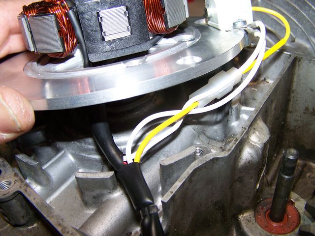
Put the new stator on the engine block.
|
||||
|
|
|||||
|
Attach the stator now with the two screws M6x25. Never use longer screws or those with higher heads. Never push it again to squeeze any cables underneath. While it was specially milled a cable shaft in the drive, but it is still very tight! |
||||
|
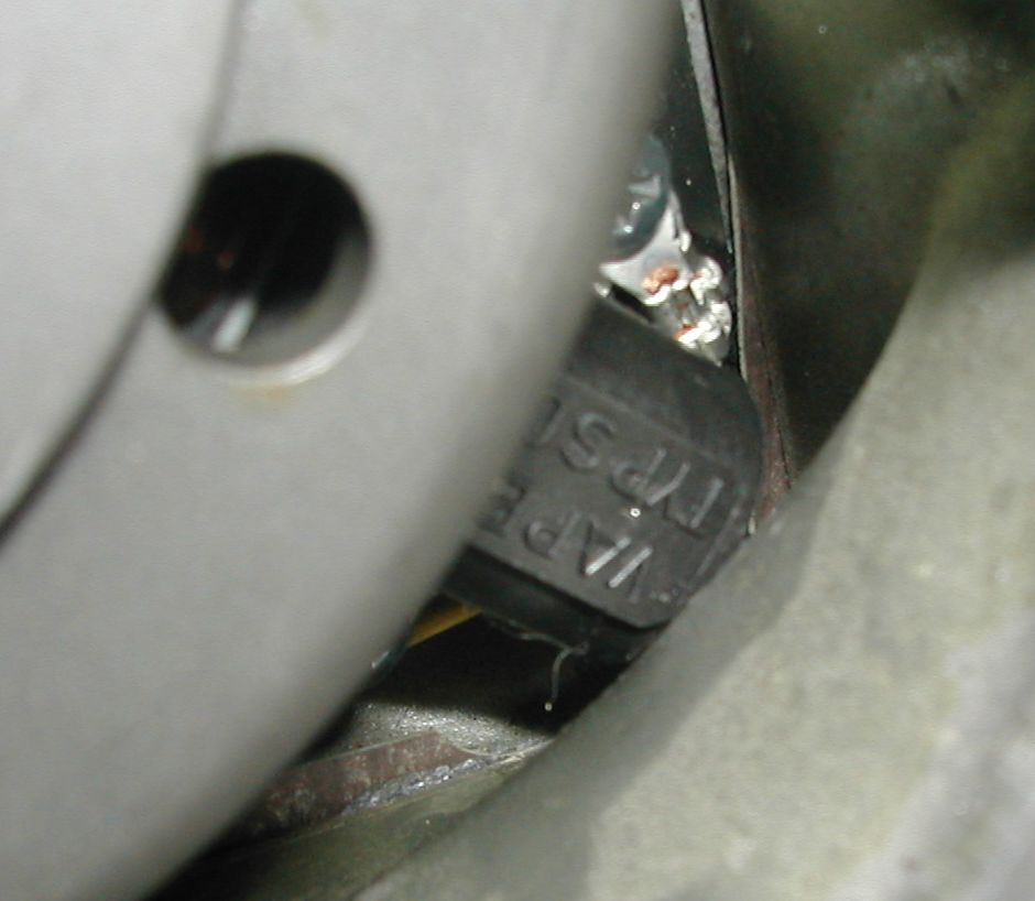
Put the lid on and check carefully that this does not press on the sensors. When it comes to lower sensor extremely tight and it may be that here you have to remove some material from the housing (cover). |
||||
|
|
||||
|
|
|||||
|
|
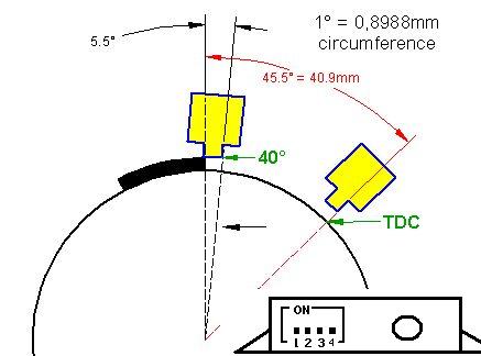
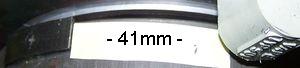
The
ignition works as follows:
At top dead center, the actuating plate is 45 ° (that is, on the outer periphery of the rotor 41 mm) away from the sensor. The timing mark should not be visible, you familiarize yourself a new one. To do this, one 41mm long strip of paper to the right edge of the plate and mark the end of the strip on the rotor. At maximum
spark advance, the left edge
of the sensor core is at the
height of the wafer. |
||||
|
|
|||||
|
Rotor in
position of maximum ignition
advance (40 ° BTDC) apply this setting only if your ignition is really to have 40 degrees BTDC FZ! |
Rotor in "OT"-Position That is the better Installation version offers the flexibility of setting |
||||
|
|
||||
|
Remove the two
spark plugs. Use
Put the new rotor by
hand to wave to
him to be able to
rotate the shaft (it is first
no matter what you put on the
rotor). Now place the crankshaft in a position in which the cylinder is left in OT. |
|||||
|
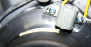
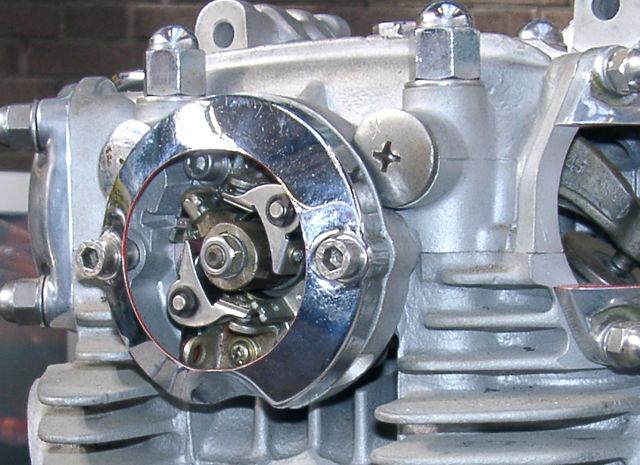
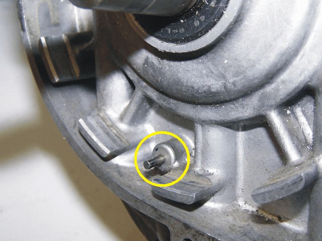
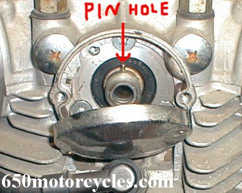
To find the
upper dead point can be
seen to the camshaft (the
end of the shaft on
which the interrupter was). There you will see a small pin (or at least a hole in the pin once was).
Foto und Idee von http://www.650motorcycles.com |
||||
|
|
|||||

|
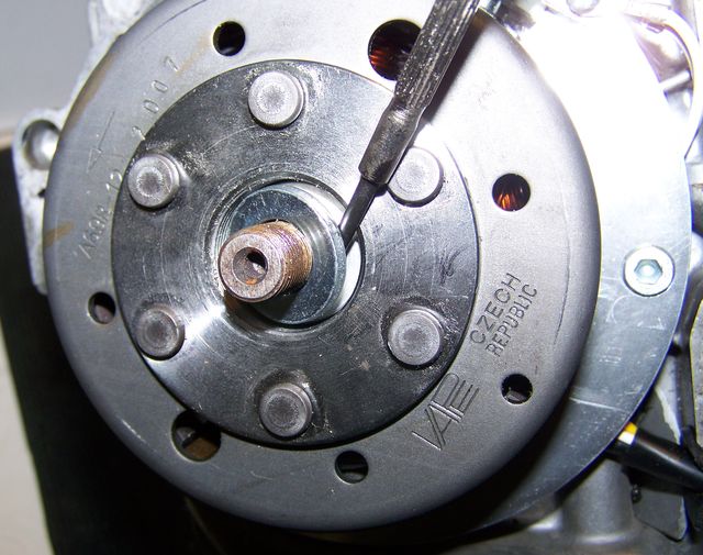
When the crankshaft
is at TDC position
of the left cylinder, pull the new
rotor with the puller again
gently. Make them
doing this, which does not change
the position of the shaft.
|
||||
|
|
|||||
 |
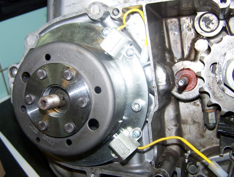
Now attach the rotor by means of the two spacers (the first aluminum, the steel washer) and the special nut.
|
||||
|
Carefully turn
the rotor by hand and check
the distance between the plates
on the rotor and the sensor
core. It should
be between 0.4 mm.
|
||||
|
|
|||||
|
If after an
initial test run, require a
different timing, you can
do this by placing the rotor
(with consistently positioned
crankshaft) differently.
If you want
to change the course of the adjustment
itself, you must choose a
different curve of the control unit.
This is done via the small
switch there.
The curves are calculated for the normal crankshaft. For the 277 shaft you might have to experiment a bit.
|
|||||
|
|
|||||
|
Please look
at the mounting
block on the
little blue button on
the top narrow side of the black Zündverstelleinheit.
Here are 4
small switches with
which different curves
programmed into the
unit can be activated.
You can choose from these curves according to your requirements. It's even the curves switch the engine running. However, the switches are not there to be constantly connected. |
|||||
 |
This setting
gives a Zündverlauf very
similar to the original break
ignition. The adjustment starts at 9 ° BTDC and adjusted linearly to 38 ° at 3,000 r / min |
||||
|
We recommend this as the first curve setting. |
|||||
|
|
|||||
 |
This setting gives you the same curve as previous, only the resulting adjustment to 38 ° only at 5,000 r / min. The curve is so flat and in our experience is not always the best. | ||||
 |
Starts at 5 °, adjusted to 40 ° at 3,000 r / min. In 8000 r / min, the motor is braked. One can not exceed 8,000. | ||||
 |
Starts at 4 ° C and adjusted to 40 ° at 3,500 r / min. | ||||
 |
Starts at 24 °, then moved quickly to 36 ° at 3,000 and then more slowly to 39 ° at 5,000 r / min. |
||||
|
|
|||||
|
For again
pulling off the new rotor,
please ONLY the
attached puller M27x1, 25 (Order
No.: 71 69 999 99)
use.
NOTE: When using a hammer or Klauenabziehers the magnets in the rotor to solve! |
||||
| Before you screw the puller, remove the steel washer. | |||||
 |
|
||||
|
|
|||||
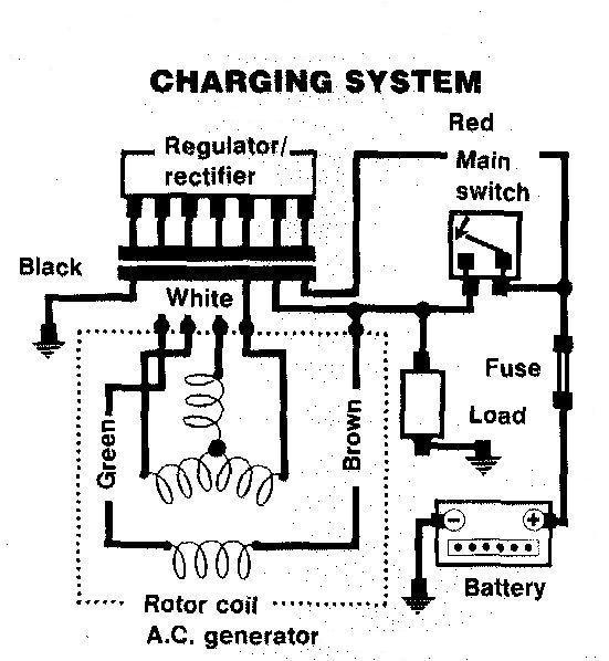
| Cabling: The system comes with its own wiring between the new components (alternator, ignition coil, regulator, controller). The
integration of the new with
the original system is at
the battery (or when driving
without battery to the
terminals, the battery went
to!) |
|||||
|
original wiring |
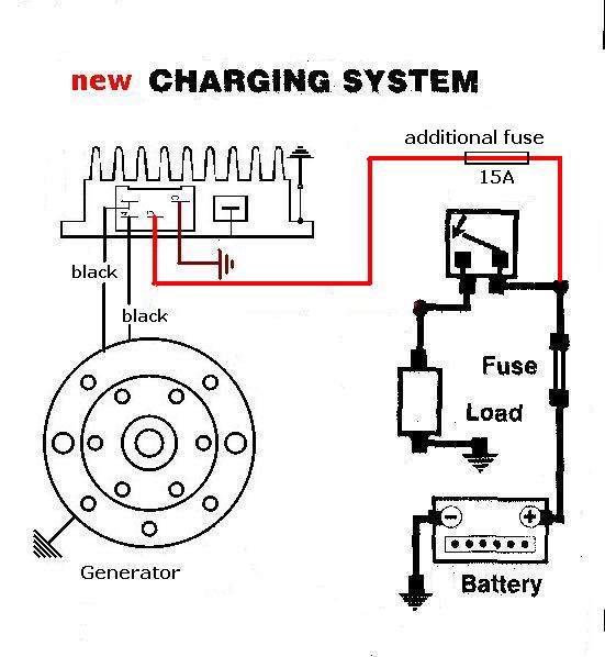
new wiring |
||||
|---|---|---|---|---|---|
 |
 |
||||
|
|
|||||
|
Connect the parts as shown in wiring diagram 9vxk12: |
|||
|
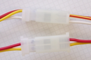
* |
On this special circuit exist each 2 of advance units, ignition coils and sensors. If connecting the plugs, please note eventually affixed (red) markings on the plugs. These plugs shall be connected. | ||
|
|
Look for the advance units with its female plugs and the three wires (red, white and yellow). Connect this plugs with the two plugs of the generator with the three wires (red, white and yellow resp. yellow/red). | ||
| * |
The second plugs at the advances (male plugs) will be connected to the plugs at the ignition coils. This two plugs can only be connected in one position. Note the changing colours: |
|
|
| * |
Important! Never run the high tension cable(s) and the cable(s) of the advance units closely in parallel (say in one shielding). This will trigger back coupling that disturbes ignition and might even damage the advance unit. |
||
|
* |
|
The new regulator/rectifier has a compact plug with 6 positions, of which one is not used (before November 2007 it were two). From November 2007 onwards a female plug cover fitting to this plug is delivered. Into this female plug you have to insert the following wires (which have terminals that snap into the plug): | |
|
* |
The two black cables leading from the generator ... |
... connect to pins 1/4 of the new regulator (from there equally black wires lead inside the unit). It does not matter which wire connects to which of the both terminals (1/4) as they carry alternating current. |
|
| * | The new brown cable with the round eye terminal ... |
... connects pin 3 of the regulator unit (from there equally a brown wire goes inside the unit) with the negative pole of the battery or (in case you drive without battery) to ground (chassis). |
|
| * |
The new red cable with the round eye terminal ... Take care: |
... connects to pin 5 of the new regulator (from there equally a red wire goes inside the unit). Here your regulated positive voltage comes out to connect to battery plus, or (in case you drive without battery) to the voltage input terminal of the main switch (ignition lock, German bikes: pin 51/30). |
|
| Make sure that you have a 16A-fuse between battery and vehicle circuitry. | |||
|
* |
The green/red wire at pin 6 of the new regulator ... Remark: |
... is for the charge control light.
You connect there the wire that formerly did run from the control light to
the original regulator. |
|
| The charge light control function is based on a transistor switch and is an additional function. Even if that should fail, the regulator might still be in ok working condition. Simple check: have the engine running, turn lights on, disconnect the battery. If you have bright lights the unit is ok. | |||
| * |
Remains the blue (sometimes blue/white) wires at the ignition coils. This are the kill (cut-off) wires.
Note: |
Connected to ground - it
will stop ignition!
This type of wiring is used in motorcycles which originally already had magneto ignition and therefore switched off by shortcircuiting against ground. Those vehicles have by design a main lock (or some kill switch) that connects a pin to ground when in OFF position (German bikes: pin 2). The blue(/white) wires of the ignition coils will be connected here. In that way the cut-off works like previously. Alternatively you could also use the provided relay. Connect pin "30" of the relay with the blue wires of both ignition coils. Pin "85" has to be connected to 12V of the mains switch. (Please see wiring diagram "alternative wiring relay"!) |
|
| * |
Screw the high tension (ignition) cable ...
Please do not use any spark amplifying cables, such as "Nology supercables" or "hot wire". This will disturb the system and possibly damage it. |
... into the ignition coil and pull over the rubber seal before
mounting the
coil (it will be easier).
Please do use the cable arriving with the pack and not any old cable. |
|
|
You will do yourself a favour to treat your bike to new spark plugs and
spark plug sockets (preferably some between 0-2kOhm).
Plenty of problems are to be traced back to "apparently good" (even
completely "brand-new") sparks plugs, terminals and cables. Do not use spark plugs with an intern suppression resistor. NGK (e.g.) offered such spark plugs coded with an "R" (for resistor). |
|||
|
* |
Finally - and before installing the battery and before the first kickstart - please re-check carefully all connections and fitments against the wiring diagram. Do check battery and light bulbs for correct voltage (12V). Should something not work, please consult our trouble-shooting guide on our homepage. As a first step disconnect the blue wire from the coil and re-test. |
||
| * |
IMPORTANT: During crank shaft repair the dynamo shaft is often
machined and gets shorter. The result is a rotor sitting lower, possibly
touching now with its rivets the stator coil. The result is a destroyed
stator and ignition failure. For more detail and how to check see (online) here. |
||
|
|
Important safety and operating information |
|
# |
Safety first! Please observe the general
health and safety regulations motor vehicle repair (MVR)
as well as the safety information and obligations indicated by the
manufacturer of your motorcycle. The timing marks on the material are for general guidance only during first installation. Please check after assembly by suitable means (stroboscope) that settings are correct to prevent damage to the engine or possibly even your health. You alone are responsible for the installation and the correctness of settings. |
|
# |
Ignition systems generate high tension! With our
material right up to 40,000 Volts! This may, if handled carelessly, not
only be painful, but outrightly dangerous.
Please do keep a safe distance to the electrode of your spark plug and
open high tension cables. Should you need to test spark firing, hold the
spark plug socket securely with some well insulating material and push
it firmly to solid ground of the engine block. Never pull sparkplug caps when engine is running. Wash your vehicle only with engine at standstill and ignition off. |
|
# |
Should you have received in the kit HT cables with a fixed rubber boot(which does not contain a resistor) you might have to use spark plugs with an inbuilt resistor (or replace the cap with one containing a resistor) to comply with your local laws. |
|
# |
After installation, please check tightness of all screws, even those preinstalled. If parts get loose during run, there will be inevitably damage to the material. We pre-assemble screws only loosely. |
|
# |
Give the newly installed system a chance to work, before you start
to check and test values, or what is worse apply changes to it. Our parts have been checked before delivery to you. You will not be able to check much anyway. At any rate do refrain from measuring the electronic components (such as ignition coil, regulator and advance unit). You risk severe damage to the inner electronics there. You will not get any tangible results from the operation anyway. Bear in mind that also your carburetor, your spark plugs and spark plug sockets (even if completely new) might be the reason for malfunction. The general experience with our systems is that the carburetor will have to be re-adjusted to lower settings. Should the system not start after assembly, first disconnect the blue (or blue/white) cut-off wire directly at the ignition coil (or in some cases advance unit) to eliminate any malfunction in the cut-off circuitry. Check ground connections carefully, make sure there is a good electrical connection between frame and engine block. In case of troubles, please consult our Knowledge Base first before you send off the material to us for checking |
|
# |
The spark of classic, points based ignition systems has with about 10,000 Volts comparatively little energy and looks therefore yellow and fat (which however makes it highly visible). The spark from our system is a high energy spark with up to 40,000 Volts and therefore is needle thin focused in form, and blue in colour, which makes it not so visible. Furthermore you get spark only at kick-start operated speeds and not by pushing the kick-lever down slowly with your hand (as you might get with battery based ignitions). |
|
# |
Systems using a twin outlet ignition coils have a few peculiarities. Please observe that during tests on one side, the other has either to be connected to an fitted spark plug or securely earthed/grounded. Otherwise there will be no spark on either side. Also with such open exits long and dangerous sparks may fly all over the coil. |
|
# |
Never do electric arc welding on the bike without completely disconnecting all parts containing semiconductors (ignition coil, regulator, advance) stator and rotor need not be taken off. The same is true for soldering. Before touching electronics disconnect the soldering iron from mains! Never use copper putty on spark plugs. |
|
# |
Electronics are very sensitive to wrong polarity. After work on the system, do check correct polarity of the battery and the regulator. Wrong polarity creates short circuits and will destroy the regulator, the ignition coil and the advance unit. As a rule, wiring will always be colour to colour. Instances, where colour jumps between wires are expressly mentioned in our instructions. |
|
# |
When you handle the new rotor, take care not to damage its magnets. Refrain from direct blows to the circumference of the rotor. When transporting never put the rotor over the stator. Observe our information relative to transport of the material. |
|
# |
Do not use spark plug sockets with a resistance of more than 5kOhm. Better use 1 or 2kOhm ones. Bear in mind that spark plug sockets do age and thereby increase their internal resistance. Should an engine start up only when cold, a defective spark plug socket and/or spark plug is very probably the cause. In case of problems check high tension cables too. Never use carbon fibre HT-cables, never use so called "hot wires" which promise to increase spark. |
|
# |
It is a good idea to cover the rotor in a thin layer of oil to reduce the risk of corrosion. |
|
# |
Never use a claw puller or a hammer to disengage the rotor. Its magnets might become loose in the event. We offer a special puller for disengaging the new rotor again (see assembly instruction)! |
|
# |
Should the motorcycle not be in use for some longer period, please disconnect the battery (so existing) to prevent current bleeding through the diodes of the regulator. Though, even a disconnected battery will empty itself after a while. |
|
# |
Please do observe these remarks, but at the same
time, don't be afraid of the installation process. Remember, that before you, thousands of
other customers have successfully installed the system. Enjoy driving your bike with its new electric heart! |
|
|