Powerdynamo brings new ignition & light
to your vintage motorcycle
![]()
![]()
![]()
![]()
|
|
Powerdynamo brings new ignition & light |
|
|||
|
|
|||||
|---|---|---|---|---|---|
|
Sorry! |
Version 12.12.2008 |
|
If you can install and time a stock ignition and
possess basic mechanical skills, you can install a Powerdynamo! |
|
| Powerdynamo can not monitor the compliance to those instructions, nor the conditions and methods of installation, operation, usage and maintenance of the system. Improper installation may result in damage to property and possibly even bodily injury. Therefore we assume no responsibility for loss, damage or cost which result from, or are in any way related to, incorrect installation, improper operation, or incorrect use and maintenance. We reserve the right to make changes to the product, technical data or assembly and operating instructions without prior notice. | |
|
|
Please read these
instructions fully and carefully before starting work on your motorcycle Please bear in mind that any modification of the material as well as own repair attempts which have not been agreed with Powerdynamo may result in a loss of warranty. Do not cut off wires. This leads to a loss of reverse polarity protection and often results in damage to electronics. Also, please take note of the information provided on the information page for this system. Check that what you have bought really corresponds to the motorcycle you have. Wrong ignition settings may damage your engine and even hurt you during kickstart (violent kickbacks). Be careful during the first test runs. If needed change settings to safer values (less advance). During assembly check carefully that the rotor (flywheel) does not touch the stator coils or anything else, which may happen due to various circumstances and lead to severe damage. |
| Designated use This system is designated to replace stock dynamo/alternator & ignition systems in vintage and classic motorcycles whose engine characteristics have not been modified aftermarket. This system is not a tuning system and it will not bring significant increases in engine output. It does however significantly enhance roadworthiness and comfort by offering better lighting, better function of side indicators and horn and, compared with the aging stock systems, increased reliability. As our system does not tamper with engine characteristics it does not increase emission of gaseous pollutants and noise. In most cases emission of pollutants should even be reduced due to better combustion. If used as designated the system therefore will not normally infringe the existing legal status of the motorcycle (this statement is valid for Germany, for other countries, please check locally against your road licensing regulations). This system is not suitable for use in competition events. If used other than the designated way, warranty will be voided and it might well be that you do not obtain the desired results or, worst you loose legal roadworthiness. The charging system is only suitable for use with rechargable 12V (6V systems 6V) lead-acid batteries with liquide electrolyte or sealed lead-acid batteries, AGM, Gel. It is not suitable for use with nickel-cadmium, nickel-metal-hydride, lithium-ion or any other types of recharchable or non rechargable batteries. This is a replacement system and not a copy of the stock material. The parts in this system therefore look different and might fit differently (notably ignition coil and regulator) requiring some adaptation by you. |
|
| During assembly imperatively start with assy of engine based parts to see that those really fit before you start fitting the external parts. In many cases customers assemble those first and thereby often modify them in breach of warranty which renders them unfit for renewed sale. Replacing old ignition systems is not a matter of taking something from a supermarket shelf as there have been very many types, versions and possibly unknown aftermarket modifications which harbour plenty of room for error. | |
| Our systems are NOT tested for use with third party electronic devices (such as GPS, mobile phones, LED lighting etc)and may cause damage to such parts. Possibly existing electronic tachometers will not work with the new system. Read our information for suitable solutions. Possibly existing safety switches and electronic valve controls are not supported. It might be that your motorcycle was originally equipped with an ignition that did limit top speed for legal reasons. The new system does not have such a facility, so check your legal situation beforehand. | |
| If you have no expertise for the installation have it done by an expert or at a specialist's workshop. Improper installation may damage the new system and your motorcycle, possibly even lead to bodily harm. | |
| Before you order a system, please check whether a puller
tool for the new rotor is included in the kit. If not,
better order it at the same time. You might want to order light bulbs,
fuse, horn,
flasher
unit etc. Never use anything other than the recommended puller tool to pull the new rotor again. Damage to the rotor as a result of use of other tools or methods is not covered by warranty. |
|
| The rotor is sensible to blows (including during transport). Before assembly, please always check for damage (on rotor without magnet plastification try to push the magnets aside with your fingers). After impact the glued in magnets might have broken loose, sticking to the rotor solely by magnetic force, so that one does not notice right away. During engine run the damage would be considerable. Before placing the rotor onto the engine, please make sure that its magnets have not collected any metal objects such as small screws, nuts and washers. That equally would lead to severe damage. | |
|
|
If you have access to the Internet, best view those instructions online. You get larger and better pictures by clicking onto them and possibly updated information. System list at http://www.powerdynamo.biz |
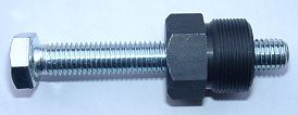 |
Pour enlever le nouveau roteur il vous fault un extracteur M27x1,25. (piece 99 99 799 00) |
|
|
|
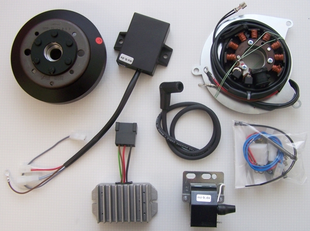 |
Vous devriez avoir reçu ces pieces. |
|
|
|
| Débranchez la batterie et enlevez-la de la moto. remplacez chacune des ampoules de 6 volts contre ceux de 12 volts. Le klaxon peut rester. Il suffira avec 12 volts. Si vous voulez utiliser une batterie, vous devez changer cela pour une version de 12 volts. Le systčme est cependant tout ŕ fait capable de courir complčtement sans batterie. | |
|
|
|
|
Débranchez tous les câbles de votre vieux générateur.
Enlevez l´ergot sur le cône au vilebrequin avec une pince. Il n'est plus nécessaire! N'oubliez pas de faire ca, autrement vous ne pourriez pas adapter le nouveau roteur correctement. Pas de crainte, l`ergot éloignée n'a pas tenu le roteur sur le vilebrequin. Il simplement vous a guidé ŕ la synchronisation correcte. |
|
|
|
|
|
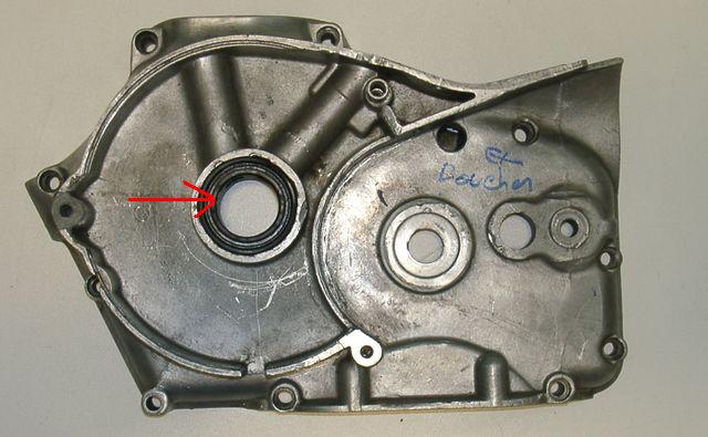
remplacer le joint au vilebrequin ŕ un avec le diamčtre interne de 28mm. |
|
|
|
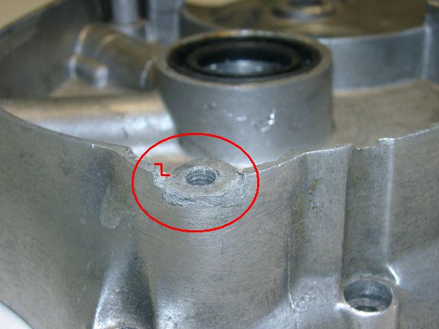
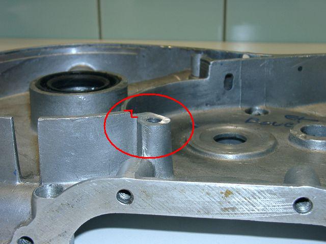
| vous devrez faire quelques petits changements sur le carter pour que la nouvelle unité se repose ŕ un égal et centré de niveau. vous doivent enlever environ 2mm du matériel au secteur de vis comme montré dans les images ici. ŕ l'attache de droite supérieure vous devrez placé le buisson d'entretoise (fourni) au-dessous du plat. | |
 |
|
|
|
|
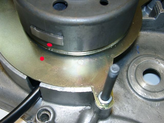
| mettez le nouveau plat sur le moteur, Fixez l'unité avec des goujons filetés et des ecrous comme vue ici. | |
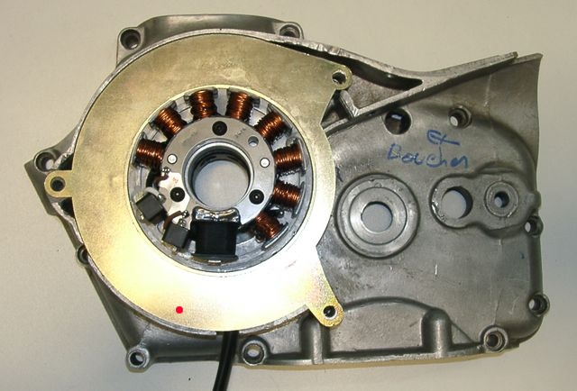 notez l'inscription rouge du plat que c'est pour la synchronisation. |

|
|
|
|

|
Regardez le nouveau roteur. Vous trouverez sur la circonférence du rotor une inscription rouge.
C'est pour la synchronisation d'allumage.
Négligez le plat élevé en métal (signe) prčs de cette inscription c'est pour d'autres systčmes et sans pertinence avec le motobecane. |
|
|
|
 (Photo shows different flywheel!) |
Eliminez la bougie. Introduisez le piston dans la position d'allumage pleine
avance (c'est sur la motobecane 8.1mm avant sa position plus élevée - PMH). Pour faire ceci, mettez le
roteur sur l'axe et employez-le comme bouton de tour.
Quand vous avez trouvé cette position, désengagez le roteur (sans changer la position du vilebrequin) et remettez-le sur l'axe de telle maničre que les deux marques sont l'un sur l'autre. Dans cette position fixez le roteur.
|
|
|
|
| Faites tourner le roteur ŕ la main et vérifiez
qu'il se déplace librement au-dessus de l'embase.
Si vous avez besoin d'une position différente d'allumage, vous pouvez placer le roteur ŕ l'agle nécessaire. |
|
|
|
|
 |
E rotor a un long axe qu'il atteint dans le nouvel (28mm) gufero
(oilseal) et fixe lŕ contre l'huile.
(Photo shows different flywheel!) |
|
|
|
 |
Éliminez les vieux supports pour le stateur ŕ l'intérieur de
salut du couvercle.
Faites attention: le matériel est flamable (magnésium). |
|
|
|
|
Fixez le nouveau régulateur, la boite electronique ( unité de
commande pour changer l'avance d'allumage en fonction de la vitesse de
vilebrequin) et la bobine d'allumage dans un
endroit commode. Par example dans un compartiment latéral comme montré ici.
Mais vous ętes libre de choisir un endroit pour les pičces. |
|
|
|
|
| Regardez l'unité de commande. elle a 4 petits commutateurs sur son supérieur proche du fil. avec ca, on régle des différentes characteristiques (en totale 16 versions) d'avance. | |
|
Recommandé pour la motobecance est une position comme
montré ici. 24° avec le commencement, alors linéairement sur 36° avec 3.000U/mn et plus loin ŕ 39° avec 5.000U/mn. |
|
|
|
|
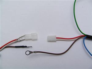
Connect the parts as shown in wiring diagram 91ik-ac: |
||
|
* |
To facilitate wire exit through the often small openings in the engine casing, the plastic plug of the generator's wiring that leads to the advance unit have not been put onto the wire terminal. You should place the plug there only once all has been properly installed on the engine side. | |
|
|
Look for the advance unit with its female plug and the two wires (red and
white).
Put the provided 2-position plug housing onto this plug and insert the two wires (red and white) from the generator. Make sure that the terminals engage securely in the housing and that you connect:
|
|
|
Should you need (or want) to get the terminals out of the plug housing again, enter a paper clip from front next to the terminals and push the little barb aside. Than pull the wire out. |
||
| * | The brown wires from the new generator and the advance unit with the round eye terminals ... | ... have to be screwed to the holder frame of the ignition coil (ground). This connection is very important. Please don't depend on the frame as the earth-connection. Varnish, oil and dirt prevent often a good contact! |
| * | The grey resp. green cable of the advance unit ... | ... is the output of the to the ignition coil and gets connected to the single male terminal there. |
| * |
Important!
Avoid prolongation of the green wire between advance unit and ignition coil.
This may lead to ignition trouble.
|
|
| * |
The blue/white wire at the advance u. This is the kill (cut-off) wire.
Note: |
Connected to ground - it
will stop ignition!
This type of wiring is used in motorcycles which originally already had magneto ignition and therefore switched off by shortcircuiting against ground. Those vehicles have by design a main lock (or some kill switch) that connects a pin to ground when in OFF position (German bikes: pin 2). The blue/white wire of the ignition coil will be connected here. In that way the cut-off works like previously. |
|
* |
|
The two black cables
leading from the new generator ...
... connect to the outer pins of the new regulator. It does not matter which wire connects to which of the 2 terminals as they carry alternating current. |
| Additional you need to contact a ground wire ... |
... to the metal holder of the regulator. Otherwise the light won't function. |
|
| The middle terminal of the regulator ... |
... will be connected to the wires for the lighting system of the motorcycle. |
|
| * |
Screw the high tension (ignition) cable ...
Please do not use any spark amplifying cables, such as "Nology supercables" or "hot wire". This will disturb the system and possibly damage it. |
... into the ignition coil and pull over the rubber seal before
mounting the
coil (it will be easier).
Please do use the cable arriving with the pack and not any old cable. |
|
You will do yourself a favour to treat your bike to new spark plugs and
spark plug sockets (preferably some between 0-2kOhm).
Plenty of problems are to be traced back to "apparently good" (even
completely "brand-new") sparks plugs, terminals and cables. Do not use spark plugs with an intern suppression resistor. NGK (e.g.) offered such spark plugs coded with an "R" (for resistor). |
||
|
* |
Finally - and before the first kickstart - please re-check carefully all connections and fitments against the wiring diagram. Do check light bulbs for correct voltage (12V). Should something not work, please consult our trouble-shooting guide on our homepage. As a first step disconnect the blue wire from the coil and re-test. |
|
| * |
IMPORTANT: During crank shaft repair the dynamo shaft is often
machined and gets shorter. The result is a rotor sitting lower, possibly
touching now with its rivets the stator coil. The result is a destroyed
stator and ignition failure. For more detail and how to check see (online) here. |
|
|
|
Important safety and operating information |
|
# |
Safety first! Please observe the general
health and safety regulations motor vehicle repair (MVR)
as well as the safety information and obligations indicated by the
manufacturer of your motorcycle. The timing marks on the material are for general guidance only during first installation. Please check after assembly by suitable means (stroboscope) that settings are correct to prevent damage to the engine or possibly even your health. You alone are responsible for the installation and the correctness of settings. |
|
# |
Ignition systems generate high tension! With our
material right up to 40,000 Volts! This may, if handled carelessly, not
only be painful, but outrightly dangerous.
Please do keep a safe distance to the electrode of your spark plug and
open high tension cables. Should you need to test spark firing, hold the
spark plug socket securely with some well insulating material and push
it firmly to solid ground of the engine block. Never pull sparkplug caps when engine is running. Wash your vehicle only with engine at standstill and ignition off. |
|
# |
Should you have received in the kit HT cables with a fixed rubber boot(which does not contain a resistor) you might have to use spark plugs with an inbuilt resistor (or replace the cap with one containing a resistor) to comply with your local laws. |
|
# |
After installation, please check tightness of all screws, even those preinstalled. If parts get loose during run, there will be inevitably damage to the material. We pre-assemble screws only loosely. |
|
# |
Give the newly installed system a chance to work, before you start
to check and test values, or what is worse apply changes to it. Our parts have been checked before delivery to you. You will not be able to check much anyway. At any rate do refrain from measuring the electronic components (such as ignition coil, regulator and advance unit). You risk severe damage to the inner electronics there. You will not get any tangible results from the operation anyway. Bear in mind that also your carburetor, your spark plugs and spark plug sockets (even if completely new) might be the reason for malfunction. The general experience with our systems is that the carburetor will have to be re-adjusted to lower settings. Should the system not start after assembly, first disconnect the blue (or blue/white) cut-off wire directly at the ignition coil (or in some cases advance unit) to eliminate any malfunction in the cut-off circuitry. Check ground connections carefully, make sure there is a good electrical connection between frame and engine block. In case of troubles, please consult our Knowledge Base first before you send off the material to us for checking |
|
# |
The spark of classic, points based ignition systems has with about 10,000 Volts comparatively little energy and looks therefore yellow and fat (which however makes it highly visible). The spark from our system is a high energy spark with up to 40,000 Volts and therefore is needle thin focused in form, and blue in colour, which makes it not so visible. Furthermore you get spark only at kick-start operated speeds and not by pushing the kick-lever down slowly with your hand (as you might get with battery based ignitions). |
|
# |
Systems using a twin outlet ignition coils have a few peculiarities. Please observe that during tests on one side, the other has either to be connected to an fitted spark plug or securely earthed/grounded. Otherwise there will be no spark on either side. Also with such open exits long and dangerous sparks may fly all over the coil. |
|
# |
Never do electric arc welding on the bike without completely disconnecting all parts containing semiconductors (ignition coil, regulator, advance) stator and rotor need not be taken off. The same is true for soldering. Before touching electronics disconnect the soldering iron from mains! Never use copper putty on spark plugs. |
|
# |
Electronics are very sensitive to wrong polarity. After work on the system, do check correct polarity of the battery and the regulator. Wrong polarity creates short circuits and will destroy the regulator, the ignition coil and the advance unit. As a rule, wiring will always be colour to colour. Instances, where colour jumps between wires are expressly mentioned in our instructions. |
|
# |
When you handle the new rotor, take care not to damage its magnets. Refrain from direct blows to the circumference of the rotor. When transporting never put the rotor over the stator. Observe our information relative to transport of the material. |
|
# |
Do not use spark plug sockets with a resistance of more than 5kOhm. Better use 1 or 2kOhm ones. Bear in mind that spark plug sockets do age and thereby increase their internal resistance. Should an engine start up only when cold, a defective spark plug socket and/or spark plug is very probably the cause. In case of problems check high tension cables too. Never use carbon fibre HT-cables, never use so called "hot wires" which promise to increase spark. |
|
# |
It is a good idea to cover the rotor in a thin layer of oil to reduce the risk of corrosion. |
|
# |
Never use a claw puller or a hammer to disengage the rotor. Its magnets might become loose in the event. We offer a special puller for disengaging the new rotor again (see assembly instruction)! |
|
# |
Should the motorcycle not be in use for some longer period, please disconnect the battery (so existing) to prevent current bleeding through the diodes of the regulator. Though, even a disconnected battery will empty itself after a while. |
|
# |
Please do observe these remarks, but at the same
time, don't be afraid of the installation process. Remember, that before you, thousands of
other customers have successfully installed the system. Enjoy driving your bike with its new electric heart! |
|
|