Powerdynamo regresa el encendido
y la luz
a su moto clßsica
![]()
![]()
![]()
![]()
![]()
![]()
![]()
![]()
|
|
Powerdynamo regresa el encendido |
|
|||
|
|
|
|
|
||
|
|
|||||
|
ĪApesadumbrado! |
versi¾n 08.11.2010 |
|
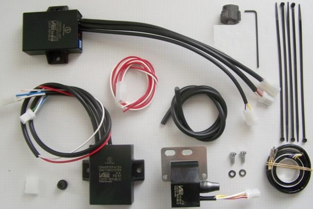
Estas partes las debe haber recibido:
|
|
|
|
|
Preparations: Make sure your bike rests securely on her centre stand, preferably on an elevated work bench and that you have good access to the front of the engine. You will have to turn the front wheel from side to side for good access. Disconnect your battery and take it out of the motorcycle for the time of work. Drain the petrol (gas) from the tank into a canister. Take care not to spill any petrol and refrain from smoking. Disconnect the tube running between the tanks sides under the frame tube. Take the petrol tank off the bike and put it to a secure place for the time of work at the bike. |
|
|
|
|
Overview of assembly: Instead of the points plate and the Bowden cable shifting (the Bowden cable may remain for optical reasons) will be mounted a Hall sensor system. This consists of a carrier ring with a built-in sensor and a magnet-based trigger unit mounted on a shaft. The function of the Bowden-cable regulation is replaced by an electronic advance unit. The CDI ignition coil requires a charging voltage of 340 volts. This will be obtained via a converter from the battery voltage of 6 volts. Without battery does not work the ignition. Assembly: |
|
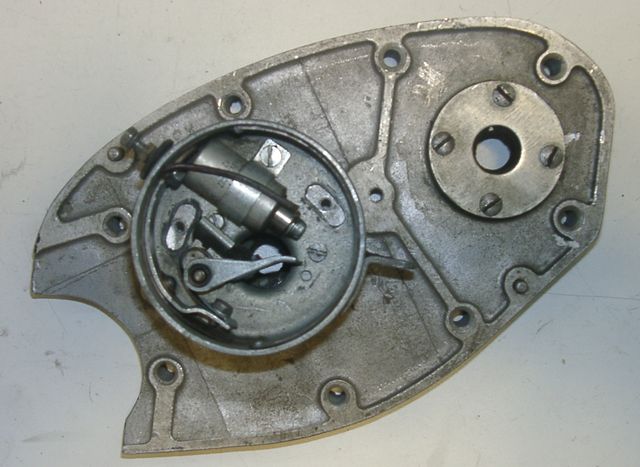 |
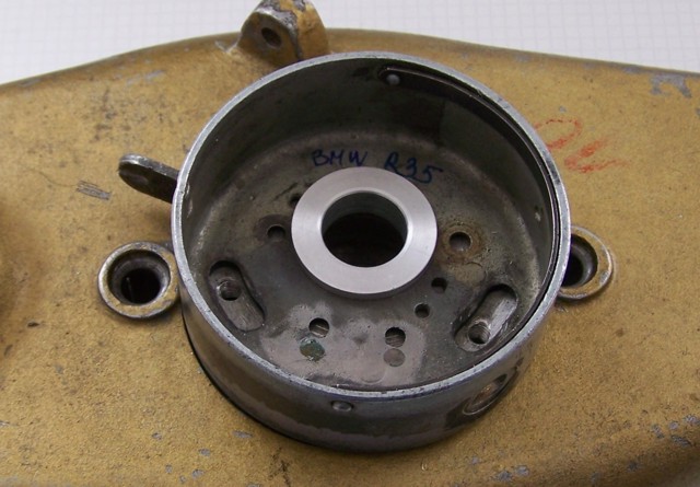
Remove the complete breaker unit from the cam shaft. Remove the points and the capacitor from the distributor housing. This housing will not rotate anymore. |
|
|
|
|
Clean the hole in the camshaft. There the shaft of the new rotor will be
glued-in.
Before you glue, check if the pin is sitting in a correct way to hold the magnet rotor so that its upper edge aligns with the upper edge of the sensor plate. |
|
|
|
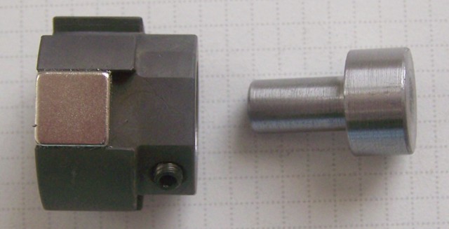 |
The rotor will mounted with two hollow set screws M4 (a appropriate Allen-key is provided). |
|
|
|
 |
Put in the centering bush. |
|
|
|
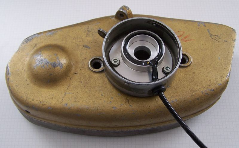 |
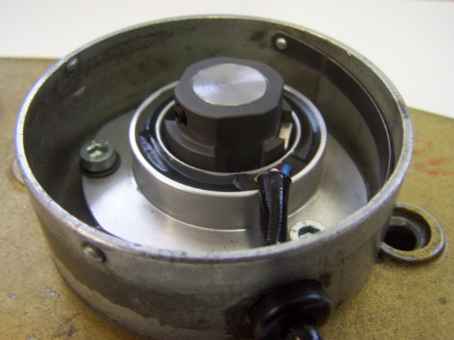
Lead the cable of the new Hall sensor through the opening of the
distributor case. Secure the cable with the grommet provided.
Screw the sensor plate with the original mounting screws and a washer. Now the bushing may not be longer rotatable. |
|
|
|
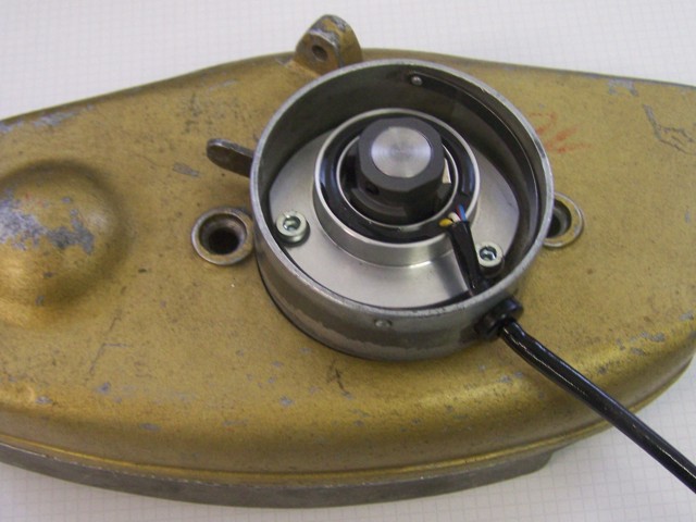 |
When the glue has cured, place the magnet rotor on the shaft. Tighten the two screws but not yet fixed, the height of the rotor must be adjusted yet. |
|
|
|
| Bevor Sie den Magnetgeber auf die nun verlõngerte Nockenwelle
verschrauben, m³ssen Sie die Kurbelwelle in eine Position 45 Grad vor OT
gebracht werden. Das sind 15.27mm Kolbenweg, also rund 15mm vor OT.
Note: This is not the ignition adjustment (this is on the R35 40░ BTDC), but a basic adjustment on this new material. Remove the spark plug and bring the piston (in compression stroke) to 15 mm BTDC. |
|
|
|
|
|
|
|
|
The curve made for this system is activated by switch 2 to ON and switches 1,3,4 away from ON (that is OFF). It gives 2░ from start up to 1.000rpm and than gradually opens to a full 40░ at 3.000rpm. |
|
|
|
| Now the system must be wired: | |