Powerdynamo regresa el encendido
y la luz
a su moto clásica
![]()
![]()
![]()
![]()
![]()
![]()
![]()
![]()
|
|
Powerdynamo regresa el encendido |
|
|||
|
|
|
|
|
||
|
|
|||||
|
ˇApesadumbrado! |
versión 24.02.2011 |
|
|
Por favor lea primero las instrucciones completamente antes de empezar con la instalación o la modificación de las piezas. Tenga en cuenta las llamadas de atención en la página de informaciones para el sistema. |
| Si no tenga conocimientos técnicos para la instalación, entonces por favor deje realizarla de una persona cualificada o de un taller técnico correspondiente. Una instalación inadecuada causa dańo tanto en el nuevo sistema como en la motocicleta. | |
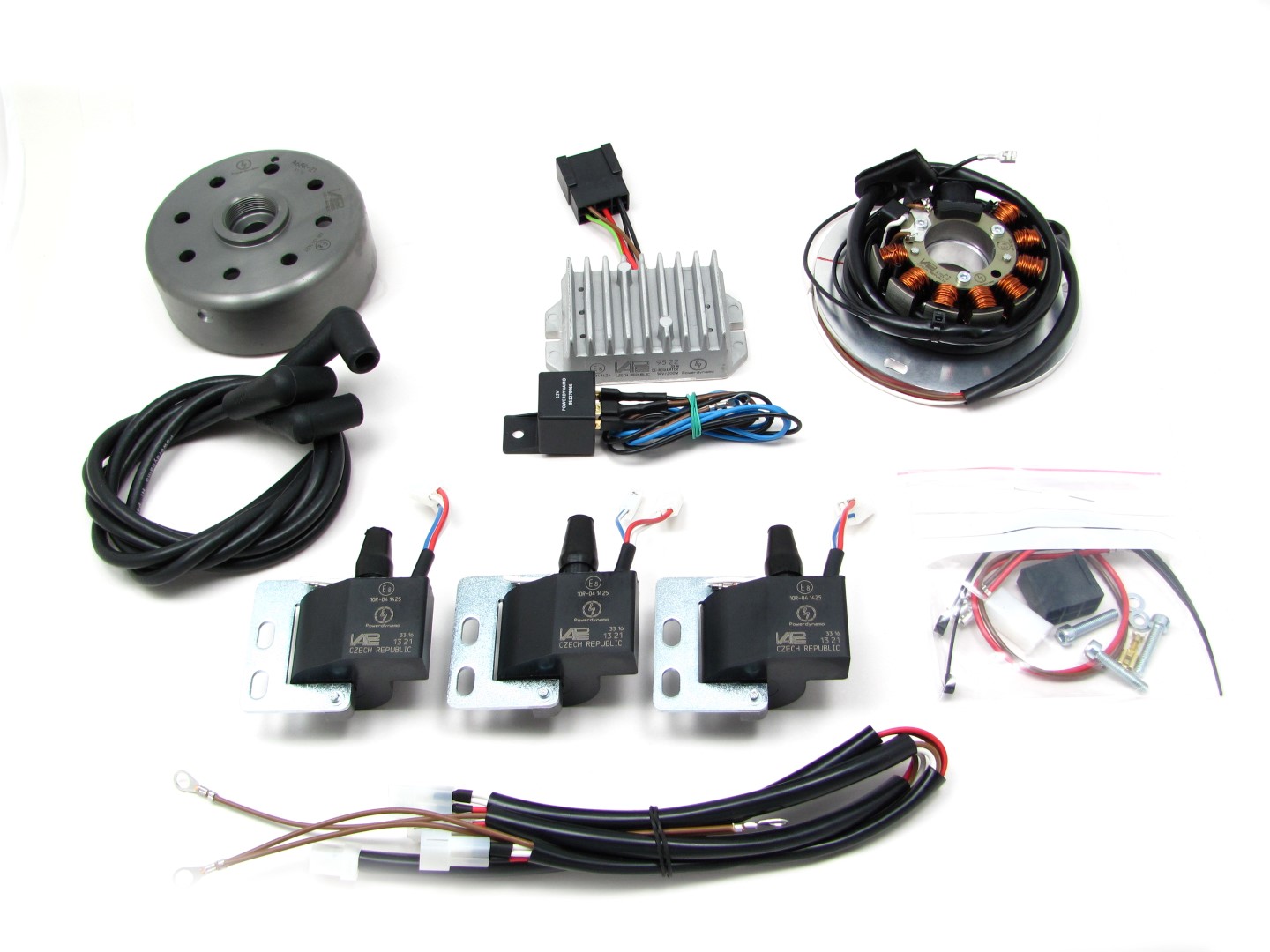
| Antes de pedir el sistema, por favor comprueba mediante la lista de paquetes (o bien la foto
"piezas en volumen de entrega") si la herramienta recomendada de nosotros para
extraer el rotor (extractor) está contenida en el volumen de
entrega. En caso negativo por lo mejor pídala también directamente.
ˇEn caso de dańo al rotor por usar otros herramientas y medios (inadecuados), el derecho de garantía
prescribe! Cuando un rotor está sentado demasiado bajo (por cualquier causa), toca y destruye la unidad de estator que está debajo. |
|
|
|
Si tiene acceso a Internet, vea esta documentación en línea. Puede ampliar los imagenes por cliquear sobre ellos y entonces recibe más
informaciones. Lista del sistema en: http://www.powerdynamo.biz |
|
|
El rotor es muy sensible a efectos de golpes (por ejemplo mientras el transporte). |
| Compruebe en cada caso antes de la instalación de la pieza el estado fijo de los magnéticos por intentar apartarlos con los dedos al
lado. Después de efectos de golpes, algunos de los magnéticos pegados podrían haberse soltados y podrían estar fijándose solamente por su poder magnético que resultaría en dańos graves en el dispositivo mientras el funcionamiento. Al mismo tiempo, por favor comruebe los magnéticos del rotor por cuerpos extrańos (por ejemplo tornillos u otros objetos metállicos). |
|
Estas partes las debe haber recib
|
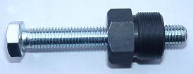 |
Para retirar el nuevo rotor necesita un extractor M27x1.25 (Número de partes: 99
99 799 00 -No
en el alcance de la fuente!-).
ATENCIÓN: ˇAl usar un extractor de garras se sueltan los imanes en el rotor! |
|
|
|
| Please note: If you drive the motorcycle with this system without battery (which is no problem for the system itself) AND use side indicators and/or electronic equipment you will have to install a large capacity condenser or opt for an alternative regulator with build in condenser to smoothen the frequency of the voltage. | |
| Make sure your Kawasaki rests securely on her stand, preferably on an elevated work bench and that you have good access to the generator side of the engine. | |
|
|
|
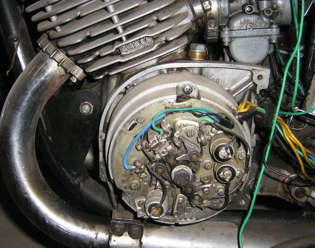 |
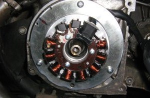
Disconnect all wires from the old generator and remove these parts. |
|
|
|
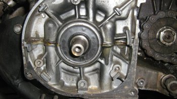 |
Take the woodruff key from the crank. You will not need it anymore. Please do not forget to do so, otherwise you will have trouble later on in the assembly. Remark: This woodruff key does not actually hold your rotor on the shaft, this is done by the cone. It simply guides to the correct setting which will now be otherwise achieved. |
|
|
|
|
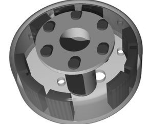
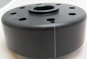
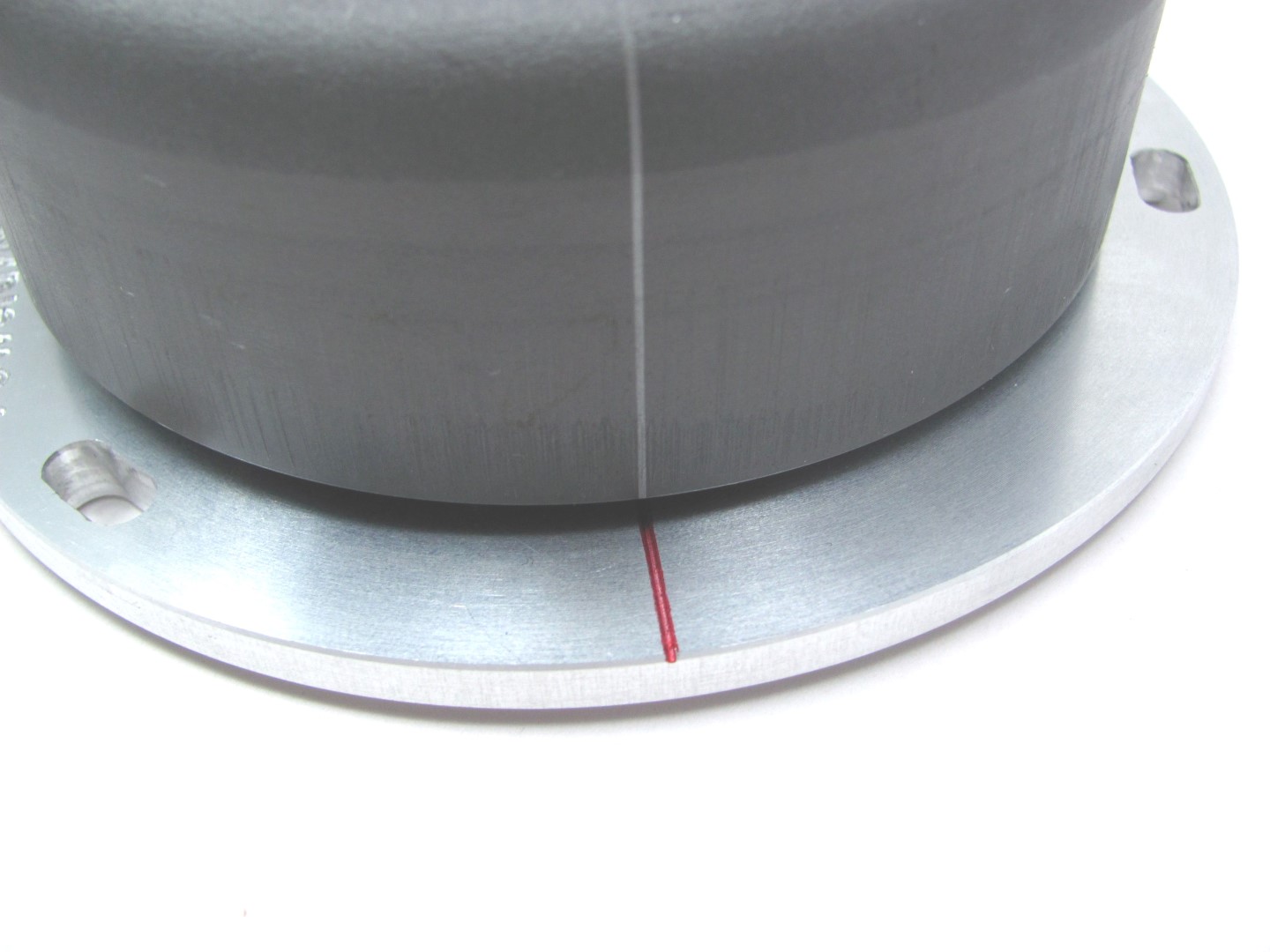
Have a look at the new rotor. You will find on its circumference a small
pressed in line. That is an ignition marking. It is durable, but not well
visible, so better highlighten it with some marker pen, preferably on top of
the flywheel.
The rotor is missing 3 magnets 120 degrees apart. This is wanted and not a defect, those magnetic holes trigger ignition. The rotor might have an arrow pointing clockwise. This is no problem, important is that the stator is made for anticlockwise turning systems, such as this Kawasaki. Check the inside of the rotor for foreign objects attracted by its strong magnets (screws or other metal parts) that could damage the rotor and stator during the operation. |
|
 |
|
|
|
|
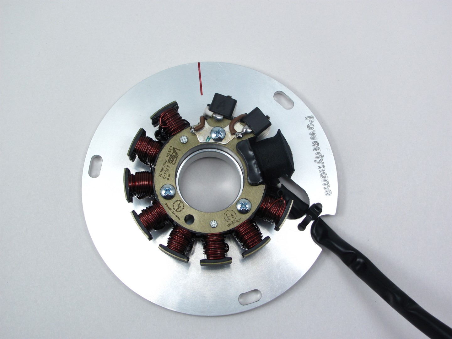 |
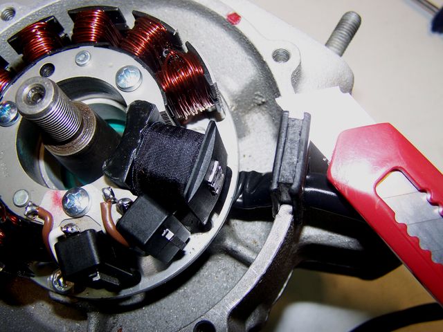
Have a look at the new stator. You will find near the black coils a small red
marking. This is an ignition
marking too.
The unit will be delivered pre-assembled. There is no reason to take the coil off. You only risk to damage the wires underneath or to set if wrongly back again. |
|
|
|
 |
Place the new stator unit onto the engine case. The thick black
coil shows about 1 o'clock. Screw down the unit with the 3 screws
M5.
ATTENTION! If you remove the stator coils but once, then make absolutely sure that the inner opening of the stator unit slots evenly over the elevated fixing rim of the base plate - otherwise the coil will sit lopsided and will touch the rotor, damaging it. The stator has to snap in rather sharply. If it sets soft, you have probably jammed a wire underneath! |
|
|
|
 |
There is a rubber grommet on the stator wire.
Press it into the wire exit opening and than cut the surplus material off carefully.
(Photo shows similar engine!) |
|
|
|
|
Ignition timing: To get maximum flexibility no groove has been put into the rotor. No need to worry over the now lost woodruff key. It did not have an arresting capacity, it was guiding to correct ignition settings. Now you have the markings and a much greater flexibility. |
|
|
|
|
| Take the spark plugs out and bring one piston (no
matter which piston) into ignition position. This
should be 3mm BTDC. You could move the piston by putting the rotor loosely onto the crank shaft and turning it. VERY IMPORTANT: ... check, that the rotor may move freely above the stator base. If (for whatever reason) a rotor/flywheel comes to sit too low (e.g. in the wake of a regeneration of the crank shaft), it will touch and destroy the stator coil under it. More info online here. |
|
 |
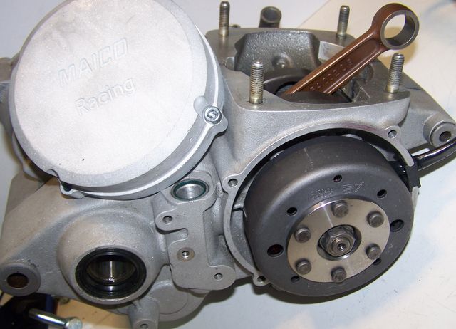
Once you have found the correct ignition point, take the rotor
carefully off again without changing the crank's position and reset
it onto the crank in such a way that the marking on the rotor aligns
with the marking on the stator. In that position fasten the rotor
carefully with the new rotor screw supplied.
Take care not to change the crank's (ignition) position. Otherwise you have to redo this procedure.
(Photo shows similar engine!) |
|
|
|
 |
In this position fasten the rotor carefully by the original nut.
Para retirar el nuevo rotor necesita un extractor M27x1.25 (Número de partes: 99 99 799 00 -No en el alcance de la fuente!-). ATENCIÓN: ˇAl usar un extractor de garras se sueltan los imanes en el rotor!
The works at the engine are finished. Screw the spark plugs in again.
(Photo shows similar engine) |
|
|
|
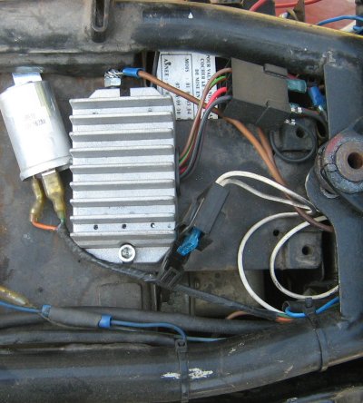
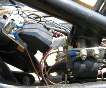
| You will now have to fasten the 3 ignition coils and
the new regulator/rectifier to the frame of the motorcycle.
You must now integrate the new lighting system into your bikes wire harness. Integration point is the connection of the red wires running to main switch and the battery. |
|
|
|
|
 |
|
|
|
|