Powerdynamo brings new ignition & light
to your vintage motorcycle
![]()
![]()
![]()
![]()
|
Powerdynamo brings new ignition & light |
|||||
|
|
|||||
| Assembly instructions for system 72 36 999 00 |
Version 05.03.2010 |
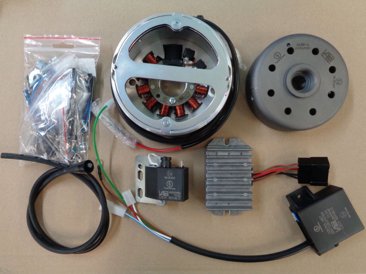 |
You should have received those parts:
|
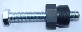 |
To pull the new rotor again, you will need a puller tool M27x1.25 (part
99 99 799 00 -Not provided!-).
Note: Never use a claw puller, a hammer or any other device, that will shake the magnets off. |
|
|
|
| Make sure your
bike rests securely on her stand, preferably on an elevated work
bench and that you have good access to the generator side of the engine.
You will have to move the front fork for good access.
Disconnect your battery and take it out of the motorcycle. Note, that you now install a 12 volt system. So you will either need a 12 volt battery or you drive without. You will still have to replace all lightbulbs to 12 volt ones. The horn may stay at 6 volts. For driving without battery, please observe our information on driving without battery. |
|
|
|
|
|
Open the dynamo cover off, disconnect the wires there and take the complete
dynamo off (see your motorcycle manual for details).
Take the bakelit tower off the dynamo.
|
|
|
|
|
 |
Put the tower onto the new housing and fasten it there with the 2 original screws. |
|
|
|
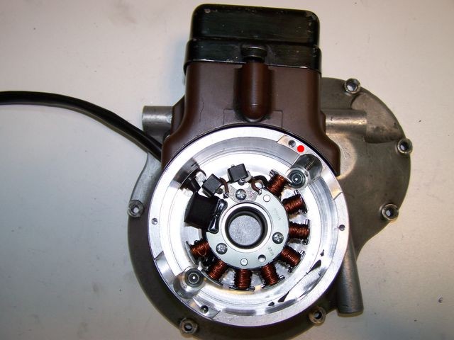
| Place the complete new unit onto the engine and fasten it there with the 2 flat screws M8 supplied. Take a little care with the grommet at the wire exit. It will sit quite tight. | |
|
|
|
|
|
 |
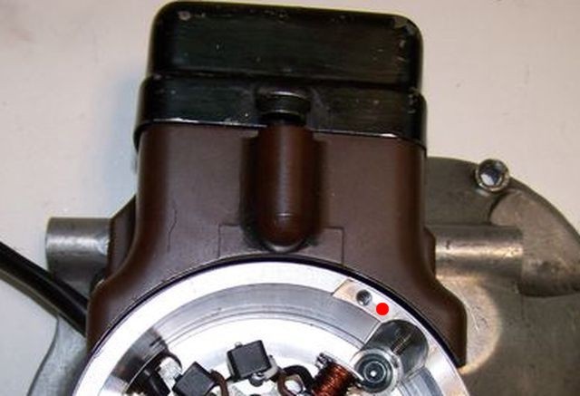
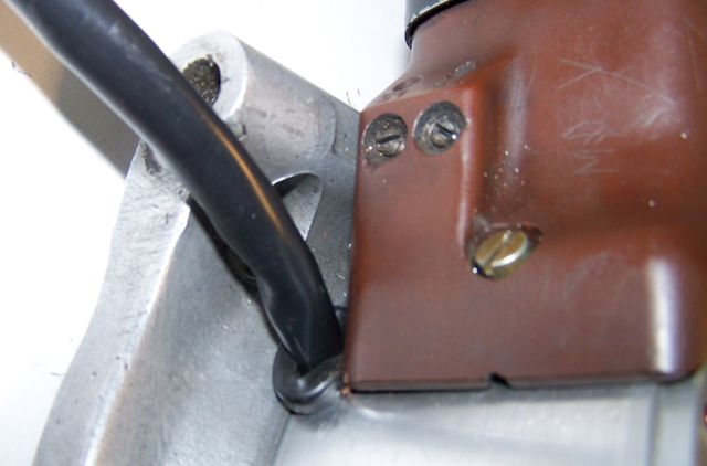
Have a look at the new dynamo body. You will find there at about the wire exit a
small red marking.
Here encircled red. This is an ignition marking. |
|
|
|
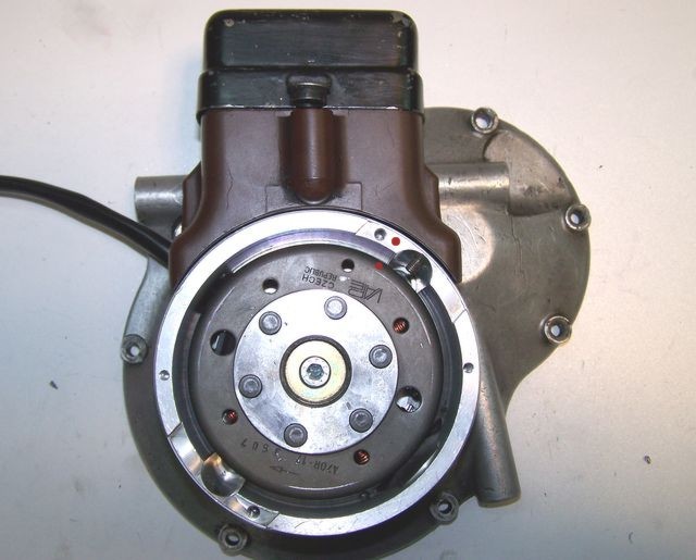 |
Have a look at the new rotor. You will find on its top edge a small red marking. This is a ignition marking too. They have to align when the engine is in top dead center position (TDC). |
|
|
|
|
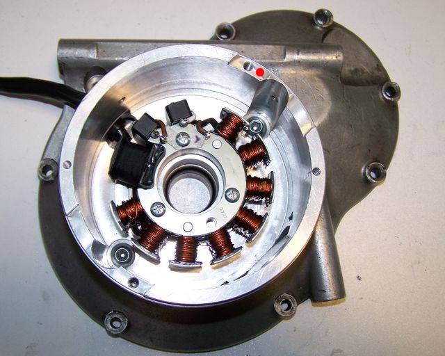
Remove the spark plug. Place the rotor loosely onto the crank and check that it may move freely
above the statorbase. PLease check this carefully. sometimes after
crankshaft repair the rotor comes to sit too low and demages the coil.
Bring the piston in TDC position (no matter in what cycle the engine is). Put the new rotor handtight on the crank shaft for turning the shaft. Once TDC is found, ake the rotor carefully off again without changing the crank's position. Than reset it onto the crank in such a way that the marking on the rotor aligns with the marking on the housing. If there is any change in the crank's position, you have to start again. This is the basic adjustment for the ignition automatic. |
|
|
|
|
|
In that
position fasten the rotor carefully with the M8x30 nut. Please don't
forget to use the washer. Screw the
spark plug back.
Now you have adjusted the ignition to standard value. Theoretically you can adjust that to any position, you have only to turn the rotor (without changing the crank shaft position).
|
|
|
|
|
| Fasten the new ignition coil, the advance unit and the new regulator at a convenient place. | |
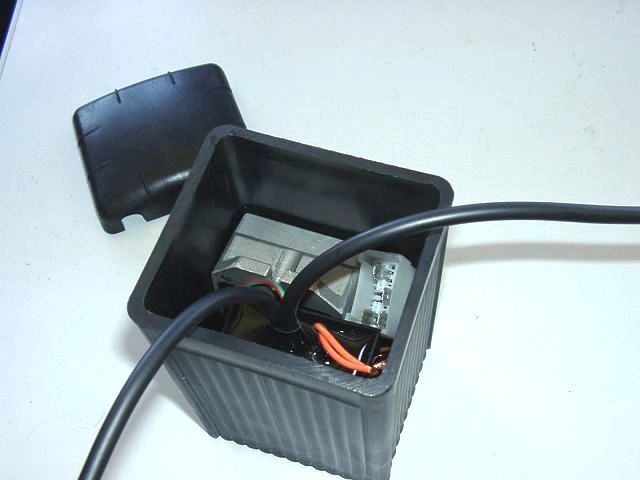 |
If you are going to drive without an battery, you may use an empty battery case to hide advance unit and regulator. |
|
|
|
| When installing the advance unit, take a look at the little blue dip-switch block on the upper narrow side of the unit. There are 4 small switches for choosing the ignition advance curves. | |
 |
The curve for the R23 (max advance of 40° at 3,000rpm) is activated by the setting shown here. |
|
|
|
|
|