Powerdynamo brings new ignition & light
to your vintage motorcycle
![]()
![]()
![]()
![]()
|
|
Powerdynamo brings new ignition & light |
|
|||
|
|
|||||
|---|---|---|---|---|---|
| ssembly instructions for system 95 19 300 S3 |
Version 18.10.2007 |
 |
If you have not already done before
ordering the system, please check the direction
of the magnetic field of your ETZ generator, to find out whether you
need, system S1 or S3.
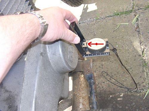
To do that, you have to start the motorcycle - something that hopefully is still possible at that stage, switch on the headlight and run the engine at about half speed (stationary!). Now hold a compass (any simple type will do) against the right side of the engine (the dynamo cover may stay in place). If the marked end of the needle points towards the engine, the S1 is OK, if the needle points however away from the engine, you need S3. |
|
|
|
 |
S3 is really the exeption and should only
be needed in motorcycles with rotors made after 1991. After that date,
unfortunately no attention had been paid to the winding direction. As a
result we get magnetic fields inversed by 180°. This interfers with our systems and leads to a rapid destruction of the ignition coil. Quite often the engine does not start and run well with the wrong polarity. |
|
Rule of thumb if you can not check
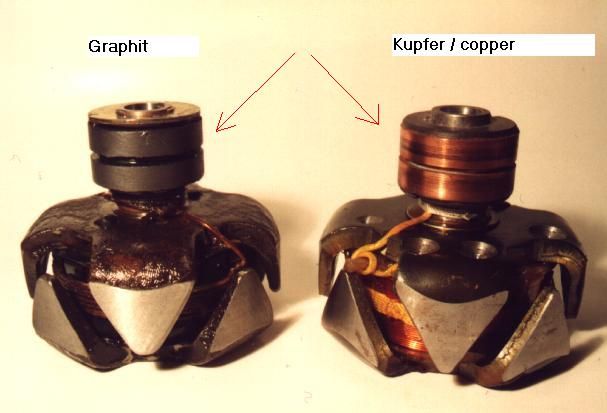
the field: If the rotor rings are made of graphite, S1 is correct, if they are made of copper, you have to employ the compass method, there is no other way of telling with those rotors!! |
|
|
|
|
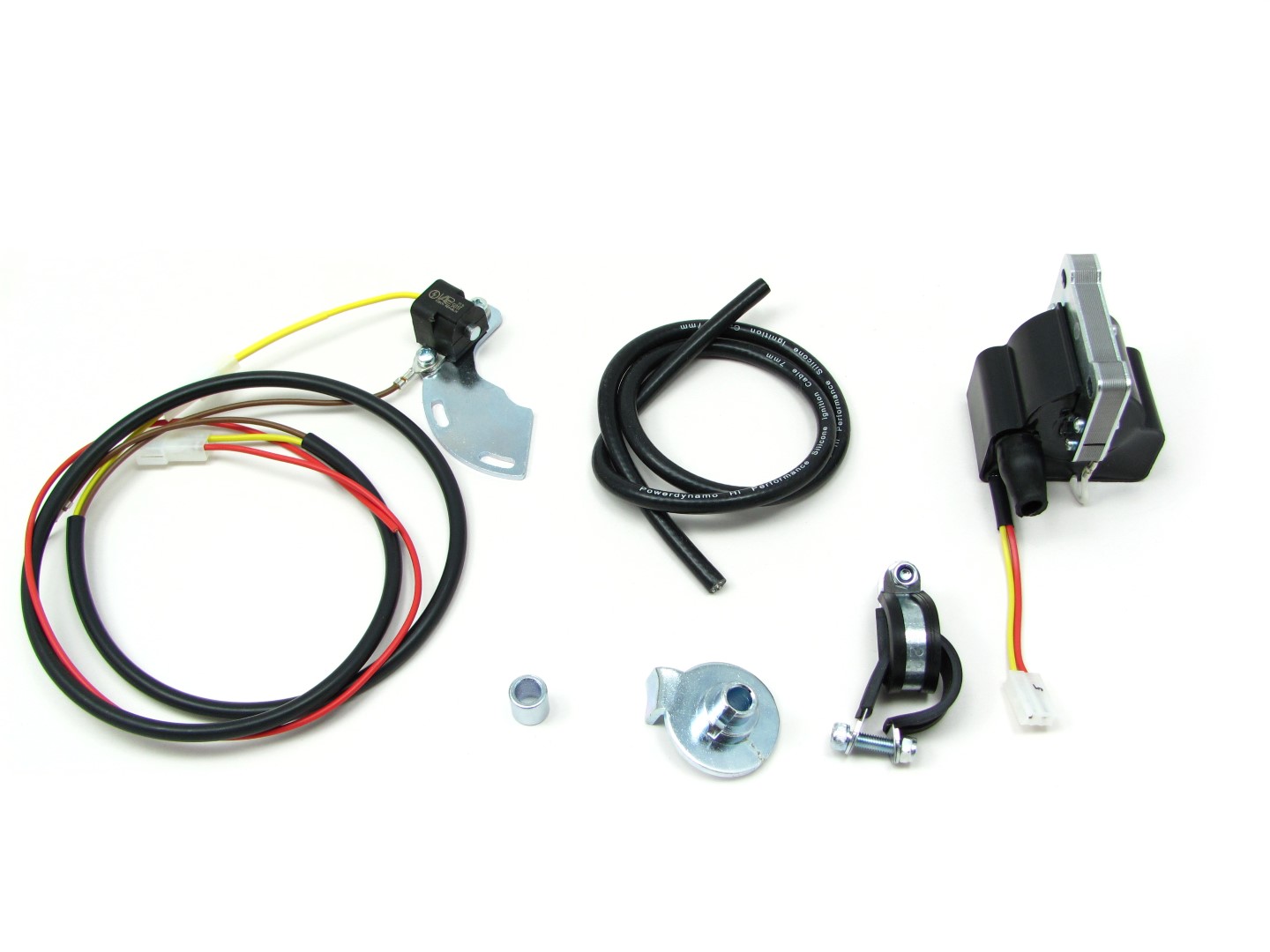 |
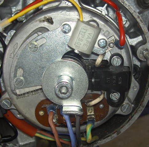
You should have received those parts! Note, that the sensor module is only loosely fixed at the base plate, as it has to be adjusted by you. Disconnect the battery and better take it off the bike for the time of work to prevent shortcircuits. |
|
|
|
| Disconnect the green wire from the points plate or whatever wires you might have at any electronic trigger there. Do not remove that wire however, you will make use of it again. | |
|
Unscrew the rotor bolt and take this long screw M7 off. Rotor ans stator
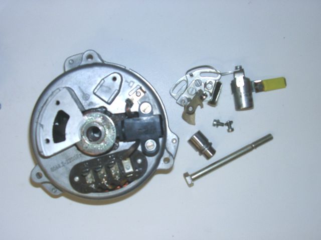
housing however remain in place. Take the cam (or whatever rotor arrangement for any electronic ignition you might have there) off. Take the points plate and the condenser off. From the parts taken off, you will only need the long screw M7. |
|
|
|
|
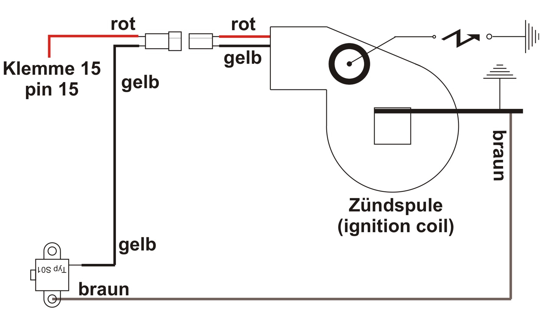
Take the original ignition coil (and so you have any ignition boxes) off
the bike. Memorize the wires that did run to your ignition coil. With the standard points based ignition those should be a green wire at pin 1 of the coil and 2 red/black wires joint in one ring-terminal at pin 15. Do not cut the 2 wires originally sitting at pin 15. Your stop/tail light would not work anymore. |
|
|
|
|
|
Now place the new holder plate with the sensor onto the generator, same
place points had been sitting. Fasten with the screws used before for the
points. Place the new rotor disc onto the rotor (in place of the cam). Put the supplied 6 washers 7.2mm on the long screw M7 and screw it back into the rotor. (The 6 washers are needed as the screw is now too long, but getting a long M7 is a headache!) |
|
|
|
| Connect the green wire, formerly attached to the points plate, with the yellow wire from the new sensor. Make sure that the contact is solid and the connection is well insulated to prevent shortcircuits to ground. | |
|
|
|
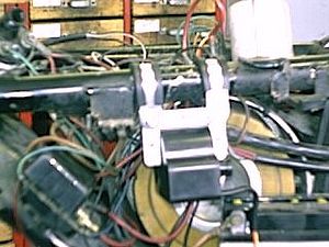 |
Fasten the new ignition coil on the rear right tube,
directly in front of where the old coil had been fixed to the frame of the ETZ.
Use the 2 supplied clamps for that. There are physical differences in the frames for the different ETZ versions. On some, you will manage only to install one clamp. In that case, use as additional holding material a cable fixer. Do not forget to put the ground wire to the coils metal frame. Without this ignition will not work. |
|
|
|
|
Now look for end of the green wire, that was
formerly on pin 1 of the ignition coil. On the engine side this wire is already
connected to the yellow of the sensor. On the coil side it now gets
connected to the yellow of the new ignition coil. The red wire of the new coil will be conected to the red/black wire, that did run before to pin 15 of the old coil (arriving from the main switch). NOTE: Any (even the briefest) confusion between the yellow and red wire of the coil will destroy it on the spot. The same is true for any mixup in connecting the battery. Never connect the batterie's plus to the frame.
|
|
|
|
|
|
Now, all is fixed and you may set timing.
Note, that you cannot check with a simple light, as you did before on
points. Never use this light check on electronic ignitions, you kill
the electronics. He, who is not happy with the below described
method should get himself a stroboscope to check. Take the spark plug out and bring the piston into top dead center position (TDC). Turn the crank shaft anticlockwise, so that the pistons falls by nearly 3mm (2.75 to be precise). There are special tools to help you, but a simple pencil and good eyesight will equally do. |
|
|
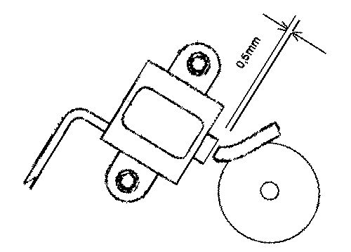 Position of rotor finger at moment of ignition. |
|
|
|
|
Check everything over again, especially
wiring. Put the battery in, connect it and start. The system should work. |
|
|
# |
Important safety and operating information! |
| # | Ignition systems generate high tension! With our material right up to 40.000 volts! This may, if handled carelessly, not only be painful, but outrightly dangerous for sensible hearts. Please do keep a safe distance to the electrode of your spark plug and open high tension cables. Should you need to test spark firing, hold the spark plug socket securely with some well insulating material and push it firmly to solid ground of the engine block to earth the output. |
| # | After installation, please check tightness of the holder screws of the sensor (if your system has one). If the sensor gets loose during run, it might come into contact with the rotors marking and get destroyed. We pre-assemble the sensor only loosely, as it has to be adjusted by you. |
| # | Give the freshly installed system the chance to work, before you start
to check and test values, or even worse before you make changes thought
to be sensible by you without having seen the system run. Our parts have been checked before delivery. You will not be able to check much anyway. At any rate do refrain from measuring the ignition coil and the advance unit. You risk several damages to the inner electronic there. You will not get any sensible results from the operation anyway. Bear in mind that also your carburettor and your spark plugs and spark plug sockets might be the reason for malfunction. The general experience with our systems is that the carburettor will have to be re-adjusted to lower settings. Should the system not start after assembly, first disconnect the blue cut-off wire directly at the ignition coil (or in some cases advance unit) to eliminate any mistake in the cut-off circuitry. Check ground connections carefully and, to be on the safe side and for testing, put an additional ground wire from the regulator directly to the engine block. |
|
# |
The spark of classical, points based, ignition systems has with about 10.000 volts only little energy and looks therefore yellow and bulky (hence well visible). The spark from our system is a high energy spark with up to 40.000 volts and therefore very sharp (needle thin focused) in form and blue in colour, which makes it not so well visible. Furthermore, you get spark only at kickstart operated revolutions and not already by pressing the kicklever down with your hand (as you might do on classic systems). |
| # | Systems using a twin outlet ignition coils have a few percularities. Please observe that during tests on one side, the other has either to be connected to an fitted spark plug or securely earthed. Otherwise there will be no spark on either side. |
|
# |
Never do electric welding on the bike without completely disconnecting all electronics. |
| # | Electronics are very sensitive to wrong polarity. After work on the system, do check correct polarity of the battery and the regulator. Wrong polarity creates short circuits and will destroy the regulator, the ignition coil and the advance unit. As a rule, wiring will always be colour to colour. Instances, where colour springs between wires are expressly mentioned in our instructions. |
|
# |
When you handle the new rotor, take care not to damage its magnets. Refrain from direct blows to the circumference of the rotor. For transport never put the rotor over the stator. |
| # | Do not use spark plug sockets with a resistance of more than 5kV. Better use 1 or 2kV ones. Bear in mind that spark plug sockets do age and thereby increase their internal resistance. Should an engine start up only when cold, a defectice spark plug socket and/or spark plug is very probably the cause. In case of problems check high tension cables too. Never use carbon fibre HT-cables. |
| # | It is a good idea to cover the rotor in a thin layer of oil to reduce the risk of corrosion. |
| # | Never use a claw puller or a hammer to disengage the rotor. Its magnets might become loose in the event. |
| # | Please do observe those remarks, but at the same time, be not afraid of installation. Remember, before you, thousands of other customers have successfully installed the system. Enjoy driving your bike with its new electric heart. |
|
|