Powerdynamo brings new ignition & light
to your vintage motorcycle
![]()
![]()
![]()
![]()
|
|
Powerdynamo brings new ignition & light |
|
|
|
||
|---|---|---|
| Assembly instructions System 70 91 999 TT |
Version 23. 10. 2007 |
|
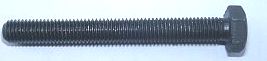
To pull the old rotor,
you will need a puller tool M10x90 (Teil Nr. 89 99 026). |
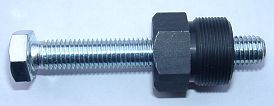 |
To pull the new rotor again, you will need a puller tool M27x1,25 (part
99 99 799 00).
Note: never use a claw puller, a hammer or any other device, that will shake the magnets off. |
|
|
|
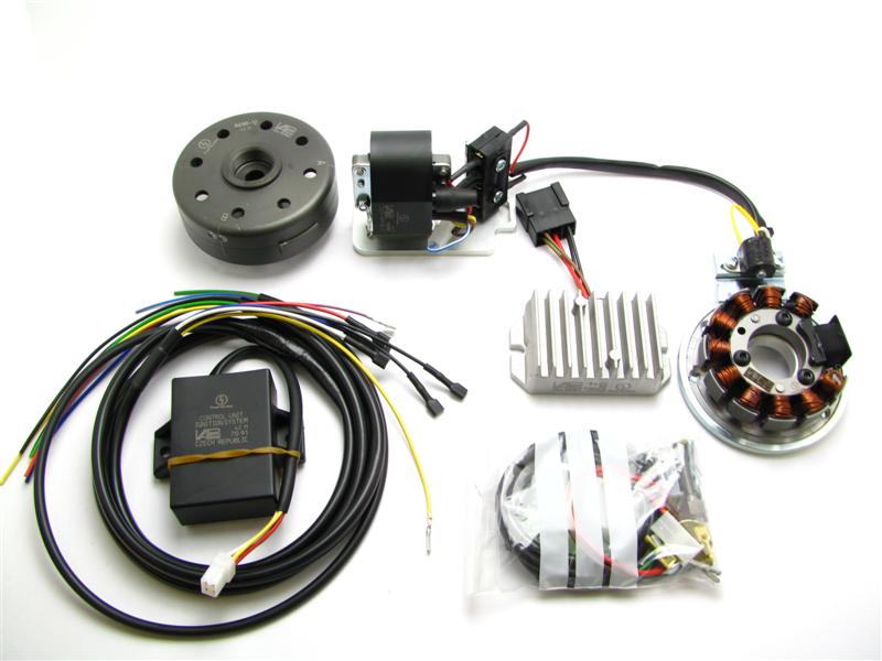 |
You should have received those parts! Please pay attention: The stator is not screwed tight on the ground plate. When you mount the ground plate on the crank case, you have to remove the stator. |
|
|
|
| Make sure your AWO
rests securely on her stand, preferably on an elevated work
bench and that you have good access to the generator side of the engine.
Disconnect your battery and take it out of the motorcycle. Note that should you be installing a 12 volt system, you will either need a 12 volt battery or you use the option of driving without. You will still have to replace all lightbulbs to 12 volt ones however in that case too. The horn may stay at 6 volts. For driving without battery, please observe our information on driving without battery. Technical it is possible to drive your bike without the battery. But consult your local road traffic regulators. |
|
|
|
|
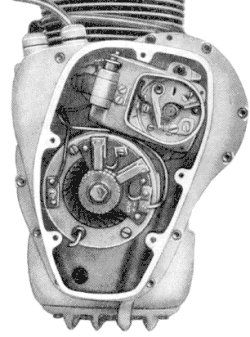 |
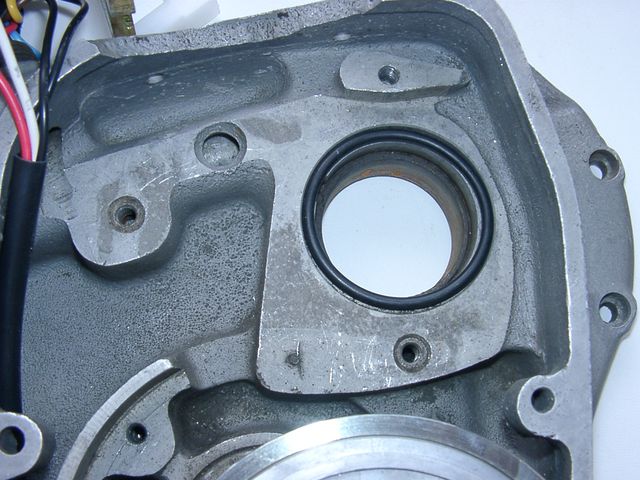
At first replace the old parts
Loose the 5 hex screws of the generator cover and take it off. Disconnect the 3 cables (normally a black one from the magneto, a red and a white one from the dynamo) and remove those parts. Pull off the old rotor with the puller tool (pay attention: the holding screw has a couter-clockwise tap, so you have to screw clockwise for pull off). Remove all 6 Volt bulbs from the head lights, speedometer and tail lights. The horn may stay. |
|
|
|
|
|
Look in the open lamp casing for the harness (3 wires are coming from the motor
to the ignition lock). Replace that harness complete.
Now you have to connect the provided short orange (mark 61) and blue/white (mark 2) cable pieces (that's only markers). The pictured cables b and d were gone to the old regulator. You will need them no more. You can disconnect and insulate them. |
| Remove the complete original harness from the
AWO, it will be replaced by new material.
If there is a regulator in the battery case, remove it too. |
|
|
|
|
|
At next you have to lead the new engine harness (with the side with the pre-assembled plugs) through the motor case from the outside to the inside of the motor (push the plugs one after another through). Screw the ignition cable in the new ignition coil, pull over the grommet and lead the cable in the motor too. The ignition coil unit hang loose on the cables, it's not screwed down. |
|
|
|
|
|
Then you have to installate the plugs on the harness. It is now easier -
the unit is not screwed down.
Take a little time for that, rather check it 3 times,
|
Put a plug on the yellow cable with the pin. Then connect it with the counterpart from the sensor (a yellow cable too). Now you have to put a plug on the pin of the blue/red cable. Plug it together with the blue/white cable from the ignition coil. It is the kill switch cable. Pay attention, don't damage the hanging loose parts: the both unit plates with its assembled parts and the cables with its plugs. |
|
|
|
|
|
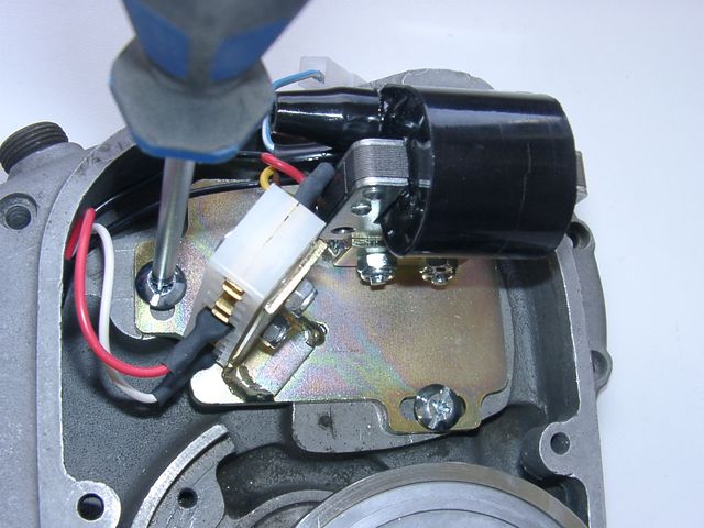
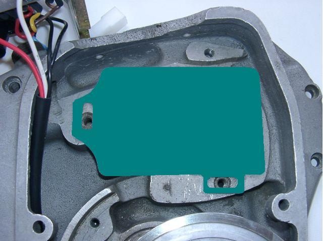
Then you have to mount the ignition coil unit. Lay the 0-ring in the opening about the cam shaft (there was the original one too). Lay on the paper seal and put on the cover plate with the ignition coil. Screw it on with the 2 screws M6x20. Screw it not tight, so you can shift the plate (if required). |
| Please note: Leave the pre-assembled plug connection of the ignition plate as they are. There is no matter to plug-off them. You risk a mal-connection, loose plugs or even tear-off cables. If you really need to pull out a plug, use a flat-pliers and handle the plug - not the cable!! | |
|
|
|
|
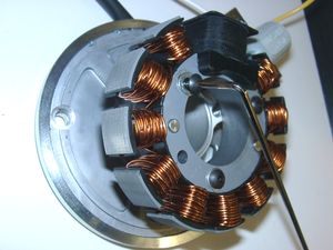
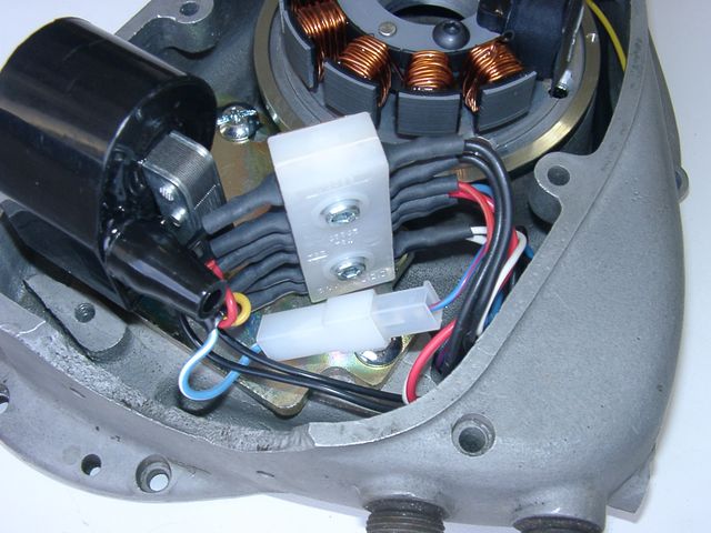
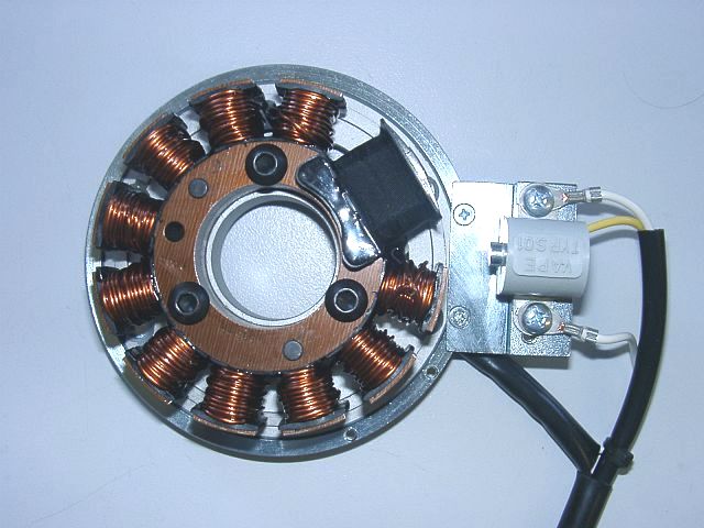
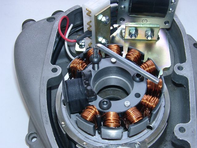
The new stator unit
is pre-assembled, so that its construction is easier to recognise. For the
mounting it has to be partly disassembled.
Pay attention: Do not damage the paint insulation of the coils. Loose the 3 hex screws, they hold the stator on the ground plate. Pull the stator in that way from the plate, so you can handle the 2 mounting holes below. |
|
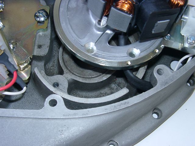
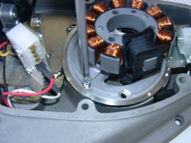
Put the pre-assembled stator plate (steel ring, aluminium plate and sensor) instead of the generator in the crank case. The sensor shows to the ground and the cable shows left upwards to the terminal of the ignition coil plate (if you look from the front on the unit). Screw down the ground plate (steel ring and inner aluminium plate) on the crank case with the 2 countersunk screws M6x30. The ignition coil unit hang loose on the cables further on. |
| Now you have to replace the stator on the ground plate. Take care, that no cable is pinched. The coil has to be fitting good on the ground plate - nearly "hearable engage". If is it ain't so, and the coil fits "soft" on the ground plate, is a cable in the way and there is a risk of damaging by contact of the rotor. Screw down the stator with the 3 hex srews M6x30. | |
|
|
|
|
|
Now pull carefully the ht-cable and the harness (6 cables) afar out of the
case, as they don't trouble the rotor.
Now you can adjust the ignition coil unit with the oblong holes (if required) and tighten the both screws. Do not forget it! |
|
|
|
 |
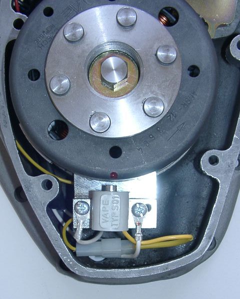
Remove the spark plugs. Place the rotor loosely onto the crank and check that it may move freely
above the statorbase. Put the new rotor handtight on the crank shaft for turning the shaft. Bring the piston into TDC. At first with the kickstarter (turning by hand) an then, for the fine adjustment, with the new rotor. You have to see the TDC marker (not the marker for the ignition point) concentric in the spy hole. |
| Take the rotor carefully off again without changing the crank's position. Reset it onto the crank in such a way that the little red marker (made by us) aligns with the left edge of the sensor bottom. In that position fasten the rotor carefully (Please don't forget to use the washer). | |
|
|
|
|
|
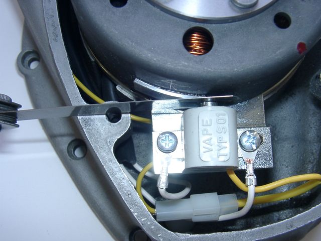
At this time you have to adjust
the gap of 0.4mm between sensor and protrusion. Turn the rotor until
the nose aligns to the sensor. Loose the holding screws of the sensor and
adjust the gap by shifting the sensor.
Don't forget to tighten the screws (also as the gap is O.K. right from the start), we don't tighten fast the screws during the preassembly! |
|
|
|
|
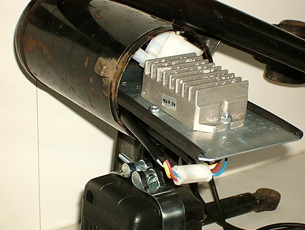
Now you have to installate the extern parts (rectifier/regulator
and the controller).
Both parts could be mounted left of the battery (here the advance unit below of the regulator/rectifier). Who wants to drive without battery, has space enough to mount it in an empty battery case, the harness is made for that (see our offer). |
|
|
|
 |
Take a look to the little blue dip-switch block at the upper flat side of the black ignition advance unit. There are 4 little switches, they are pre-positioned by us. They select the correct ignition advance curve. Please don't change the switch position and check it after the work. All switches has to be OFF (must shown to the digit). Otherwise your system will not (or not really) function. |
|
|
|
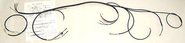 |
Now you have to lay the harness on the frame.
Note the enclosed cable guide. |
| Fasten the new harness at first loosely at the frame and connect the several cables to the corresponding electrically components (e.g. ignition lock, tail light etc). | |
|
|
|
|
|
Ignition lock cables: In the lamp casing you have to change the cable markers (hopefully you have they installed) against the cables of the same colour.
|
|
|
|
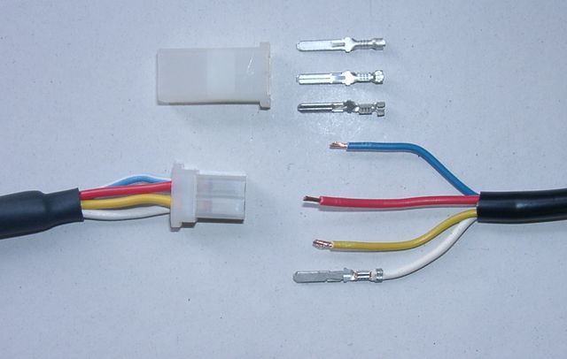 |
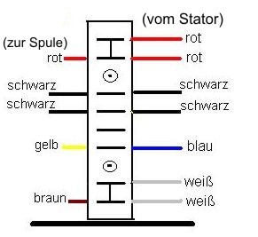
Controller unit cables: These are the red, yellow, blue and white cables from the harness of the generator. After shorting the cables on the needful length (Tour or Sport) you have to clamp the wire-end-terminals. You will have to insert the wire-end-terminals into the plastic plug, paying attention to their position there
|
|
|
|
|
Regulator cables: The green cable get a wire-end-terminal and a plastic plug. Connect it with the single green/red cable from the regulator (ignition control). If you drive without a battery , that cable remains idle. |
|
 Seen from the rear (cable) side |
The plastic plug (6 terminals):
|
You will have to
insert the wire-end-terminals into the plastic plug, paying attention to
their position there
If you like to drive with the battery, connect the brown cable with the negative and the red cable with the positive pole of the battery. These are additional connections. Don't extract the original battery (ht) cables, your system will have no power. |
|
|
|