Connect the parts as shown in the respective wiring diagram!
For our standard DC regulator (95 22 699 06), use the wiring diagram 72xr12:
For our DC regulator with built in smooting condenser (73 00 799 50), use additional the wiring diagram reg_102:

*

To facilitate wire exit through the often small openings in the engine casing, the plastic plug of the generator's wiring that leads to the ignition coil have not been put onto the wire terminal. You should place the plug there only once all has been properly installed on the engine side.
 

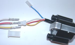
Look for the ignition coil with its female plug and the three wires (red, yellow and white).

Put the provided 4-position plug housing onto this plug and insert the three wires (red, yellow and white) from the generator. Make sure that the terminals engage securely in the housing and that you connect:

  • red to red
  • yellow to yellow
  • white to white
 

Should you need (or want) to get the terminals out of the plug housing again, enter a paper clip from front next to the terminals and push the little barb aside. Than pull the wire out.

* Connecting Powerdynamo alternator to lighting circuit (via regulator):
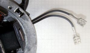
  The 2 black wires running from the stator coil carry the voltage for lights, horn, flashers etc. They have nothing 
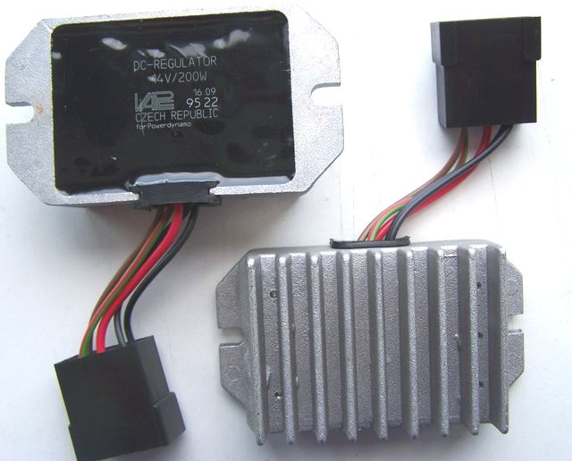
to do with ignition.

This voltage (something between 10 and 50 volts AC) has however to be stabilized (regulated) and for most uses rectified into direct current (DC) as it primarily is alternating current (AC).

For this we offer 2 different regulators:

  Attention: Any confusion between plus and minus (with the DC versions) leads to immediate destruction of the regulator. This will not constitute a warranty case as it is negligence! One can recognize a burnt regulator mostly by its sharp smell.

*

Regulator type 1: with standard DC regulator (95 22 699 06), use the wiring diagram 72xr12:

*

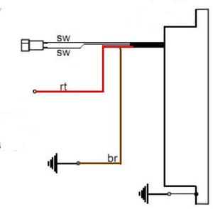
The new regulator/rectifier has a compact plug with 6 positions, of which one is not used. A female plug cover fitting to this plug is delivered. Into this female plug you have to insert the following wires (which have terminals that snap into the plug):
  The two black cables leading from the generator ...

... connect to pins 1/4 of the new regulator (from there equally black wires lead inside the unit). It does not matter which wire connects to which of the both terminals (1/4) as they carry alternating current.

  The new brown cable with the round eye terminal  ...

... connects pin 3 of the regulator unit (from there equally a brown wire goes inside the unit) with the negative pole of the battery or (in case you drive without battery) to ground (chassis).


The new red cable with the round eye terminal ...

Take care:
Wrong polarity will damage the electronics!

... connects to pin 5 of the new regulator (from there equally a red wire goes inside the unit). Here your regulated positive voltage comes out to connect to battery plus, or (in case you drive without battery) to the voltage input terminal of the main switch (ignition lock, German bikes: pin 51/30).

  Make sure that you have a 16A-fuse between battery and vehicle circuitry.
 

The green/red wire at pin 6 of the new regulator ...

Remark:
Until November 2007 this wire has been a single wire outside the compact plug.

... is for the charge control light. You connect there the wire that formerly did run from the control light to the original regulator.

Sure that this control only functions with a battery present. Should you drive without battery but still connect the wire, you will see that the light glows even as the generator generates voltage. So without battery, do not connect it.

  The charge light control function is based on a transistor switch and is an additional function. Even if that should fail, the regulator might still be in ok working condition. Simple check: have the engine running, turn lights on, disconnect the battery. If you have bright lights the unit is ok.
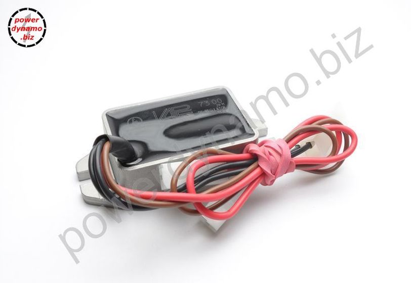
* Regulator type 2: with DC regulator with built in smooting condenser (73 00 799 50), use additional the wiring diagram reg_102:


  • the 2 black (sw) wires are the AC input from the alternator (as it is AC it does not matter which black to which black)
  • the red (rt) wire is the 12V DC output plus
  • the brown (br) wire is gound, internally connected to housing
*

Remains the blue (sometimes blue/white) wire at the ignition coil. This is the kill (cut-off) wire.

Connected to ground - it will stop ignition!

Note:
Should you experience ignition failures, disconnect as a first measure this blue wire. In  many cases that will permit you to get mobile again (particulars see: technical help)!

Switch off via separate kill switch
(when driving without battery):
The relay will not be fitted. The blue(/white) cable of the ignition coil will be connected to a kill switch, closing against ground (a button at the handlebars). Or you mount an ignition lock that has a facility to connect against ground when in OFF position.

Battery method:
Connect the brown relay wire to good ground. Lead the longer black wire from the relay to the wire that did run previously to a pin carrying voltage when the switch is on (in German bikes: pin 15) and connect it there. 
Connect the blue wire from pin 30 of the relay to the blue(/white) wire at the new ignition coil.
should your battery fail on the road, just disconnect that blue wire and your bike will run again (it will now only not stop by switching off).

 
Relay wiring
(if used):

The brown wire with the ring terminal from pins 87a und 86 goes to ground.

The black wire from pin 85 goes to a main switch terminal carrying voltage if switched on.

*


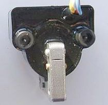
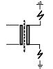
In our twin outlet coils both ends of the secondary go to the spark plugs.

Typical resistance between both exits is 6.2kOhm. Both exists fire at the same time (as many twin systems do). Sparks will be polarised however at a 180 degrees difference which might manifest when you strobe it.

  Ignition will only work correctly if both plug terminals are connected. You may not test one side with the other open (not sitting on the mounted spark plug). This is because (effectively) each exit uses ground from the other. That means also that both plugs are working in serial, adding resistances, so better use low resistance spark plug (resistor) sockets and make sure they are good. If in doubt, measure resistance on a hot socket (warm it up before measuring).

Is the flow from ground of one side via spark plug there, via coil, to the other spark plug and its ground interrupted you get no spark - on neither side. If you really want to test only one side, put the HT wire of the other to ground (earth it) than it will work. Sometimes a coil deprived of its ground from the other side searches for a substitute - with some solid fireworks around it to the chassis.

* Screw the high tension (ignition) cable ...

Please do not use any spark amplifying cables, such as "Nology supercables" or "hot wire". This will disturb the system and possibly damage it.

... into the ignition coil and pull over the rubber seal before mounting the coil (it will be easier).

Please do use the cable arriving with the pack and not any old cable.

  You will do yourself a favour to treat your bike to new spark plugs and spark plug sockets (preferably some between 0-2kOhm). Plenty of problems are to be traced back to "apparently good" (even completely "brand-new") sparks plugs, terminals and cables.
Do not use spark plugs with an intern suppression resistor. NGK (e.g.) offered such spark plugs coded with an "R" (for resistor).

*

Finally - and before installing the battery and before the first kickstart - please re-check carefully all connections and fitments against the wiring diagram. Do check battery and light bulbs for correct voltage (12V).

Should something not work, please consult our trouble-shooting guide on our homepage. As a first step disconnect the blue wire from the coil and re-test.

* IMPORTANT: During crank shaft repair the dynamo shaft is often machined and gets shorter. The result is a rotor sitting lower, possibly touching now with its rivets the stator coil. The result is a destroyed stator and ignition failure.
For more detail and how to check see (online) here.


Important safety and operating information

#

Safety first! Please observe the general health and safety regulations motor vehicle repair (MVR) as well as the safety information and obligations indicated by the manufacturer of your motorcycle.
The timing marks on the material are for general guidance only during first installation. Please check after assembly by suitable means (stroboscope) that settings are correct to prevent damage to the engine or possibly even your health. You alone are responsible for the installation and the correctness of settings.

#

Ignition systems generate high tension! With our material right up to 40,000 Volts! This may, if handled carelessly, not only be painful, but outrightly dangerous. Please do keep a safe distance to the electrode of your spark plug and open high tension cables. Should you need to test spark firing, hold the spark plug socket securely with some well insulating material and push it firmly to solid ground of the engine block.
Never pull sparkplug caps when engine is running. Wash your vehicle only with engine at standstill and ignition off.

#

Should you have received in the kit HT cables with a fixed rubber boot(which does not contain a resistor) you might have to use spark plugs with an inbuilt resistor (or replace the cap with one containing a resistor) to comply with your local laws.

#

After installation, please check tightness of all screws, even those preinstalled. If parts get loose during run, there will be inevitably damage to the material. We pre-assemble screws only loosely.

#

Give the newly installed system a chance to work, before you start to check and test values, or what is worse apply changes to it.
Our parts have been checked before delivery to you. You will not be able to check much anyway. At any rate do refrain from measuring the electronic components (such as ignition coil, regulator and advance unit). You risk severe damage to the inner electronics there. You will not get any tangible results from the operation anyway. Bear in mind that also your carburetor, your spark plugs and spark plug sockets (even if completely new) might be the reason for malfunction. The general experience with our systems is that the carburetor will have to be re-adjusted to lower settings. Should the system not start after assembly, first disconnect the blue (or blue/white) cut-off wire directly at the ignition coil (or in some cases advance unit) to eliminate any malfunction in the cut-off circuitry. Check ground connections carefully, make sure there is a good electrical connection between frame and engine block.
In case of troubles, please consult our Knowledge Base first before you send off the material to us for checking

#

The spark of classic, points based ignition systems has with about 10,000 Volts comparatively little energy and looks therefore yellow and fat (which however makes it highly visible). The spark from our system is a high energy spark with up to 40,000 Volts and therefore is needle thin focused in form, and blue in colour, which makes it not so visible. Furthermore you get spark only at kick-start operated speeds and not by pushing the kick-lever down slowly with your hand (as you might get with battery based ignitions).

#

Systems using a twin outlet ignition coils have a few peculiarities. Please observe that during tests on one side, the other has either to be connected to an fitted spark plug or securely earthed/grounded. Otherwise there will be no spark on either side. Also with such open exits long and dangerous sparks may fly all over the coil.

#

Never do electric arc welding on the bike without completely disconnecting all parts containing semiconductors (ignition coil, regulator, advance) stator and rotor need not be taken off. The same is true for soldering. Before touching electronics disconnect the soldering iron from mains! Never use copper putty on spark plugs.

#

Electronics are very sensitive to wrong polarity. After work on the system, do check correct polarity of the battery and the regulator. Wrong polarity creates short circuits and will destroy the regulator, the ignition coil and the advance unit. As a rule, wiring will always be colour to colour. Instances, where colour jumps between wires are expressly mentioned in our instructions.

#

When you handle the new rotor, take care not to damage its magnets. Refrain from direct blows to the circumference of the rotor. When transporting never put the rotor over the stator. Observe our information relative to transport of the material.

#

Do not use spark plug sockets with a resistance of more than 5kOhm. Better use 1 or 2kOhm ones. Bear in mind that spark plug sockets do age and thereby increase their internal resistance. Should an engine start up only when cold, a defective spark plug socket and/or spark plug is very probably the cause. In case of problems check high tension cables too. Never use carbon fibre HT-cables, never use so called "hot wires" which promise to increase spark.

#

It is a good idea to cover the rotor in a thin layer of oil to reduce the risk of corrosion.

#

Never use a claw puller or a hammer to disengage the rotor. Its magnets might become loose in the event. We offer a special puller for disengaging the new rotor again (see assembly instruction)!

#

Should the motorcycle not be in use for some longer period, please disconnect the battery (so existing) to prevent current bleeding through the diodes of the regulator. Though, even a disconnected battery will empty itself after a while.

#

Please do observe these remarks, but at the same time, don't be afraid of the installation process. Remember, that before you, thousands of other customers have successfully installed the system.
Enjoy driving your bike with its new electric heart!