Powerdynamo regresa el encendido
y la luz
a su moto clásica
![]()
![]()
![]()
![]()
![]()
![]()
![]()
![]()
|
|
Powerdynamo regresa el encendido |
|
|||
|
|
|
|
|
||
|
|
|||||
|
ˇApesadumbrado! |
versión 30.04.2010 |
|
|
Por favor lea primero las instrucciones completamente antes de empezar con la instalación o la modificación de las piezas. Tenga en cuenta las llamadas de atención en la página de informaciones para el sistema. |
| Si no tenga conocimientos técnicos para la instalación, entonces por favor deje realizarla de una persona cualificada o de un taller técnico correspondiente. Una instalación inadecuada causa dańo tanto en el nuevo sistema como en la motocicleta. | |
| Antes de pedir el sistema, por favor comprueba mediante la lista de paquetes (o bien la foto
"piezas en volumen de entrega") si la herramienta recomendada de nosotros para
extraer el rotor (extractor) está contenida en el volumen de
entrega. En caso negativo por lo mejor pídala también directamente.
ˇEn caso de dańo al rotor por usar otros herramientas y medios (inadecuados), el derecho de garantía
prescribe! Cuando un rotor está sentado demasiado bajo (por cualquier causa), toca y destruye la unidad de estator que está debajo. |
|
|
|
Si tiene acceso a Internet, vea esta documentación en línea. Puede ampliar los imagenes por cliquear sobre ellos y entonces recibe más
informaciones. Lista del sistema en: http://www.powerdynamo.biz |
|
|
El rotor es muy sensible a efectos de golpes (por ejemplo mientras el transporte). |
| Compruebe en cada caso antes de la instalación de la pieza el estado fijo de los magnéticos por intentar apartarlos con los dedos al
lado. Después de efectos de golpes, algunos de los magnéticos pegados podrían haberse soltados y podrían estar fijándose solamente por su poder magnético que resultaría en dańos graves en el dispositivo mientras el funcionamiento. Al mismo tiempo, por favor comruebe los magnéticos del rotor por cuerpos extrańos (por ejemplo tornillos u otros objetos metállicos). |
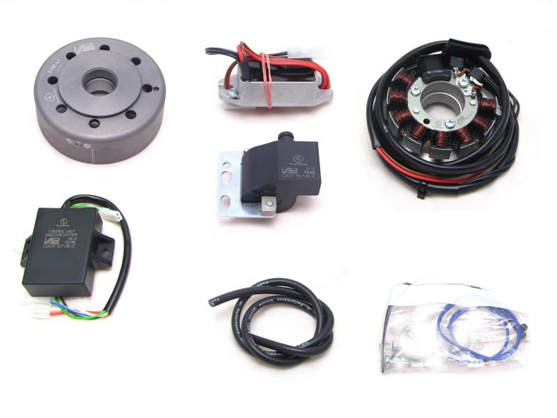 |
Estas partes las debe haber recibido:
|
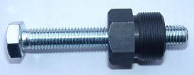 |
Para retirar el nuevo rotor necesita un extractor M27x1.25 (Número de partes: 99
99 799 00 -No
en el alcance de la fuente!-).
ATENCIÓN: ˇAl usar un extractor de garras se sueltan los imanes en el rotor! |
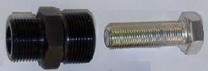 |
To pull the old rotor, you need a puller screw.
-No en el alcance de la fuente!- |
|
|
|
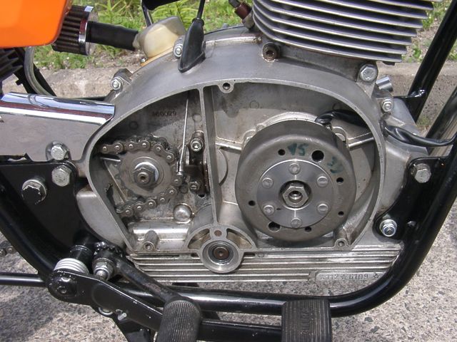
| Make sure your Gilera rests securely on her centre stand, preferably on an elevated work bench and that you have good
access to the generator side of the engine. Disconnect your battery and take it out of the motorcycle. Note that you will install a 12 volts system, so you will either need a 12 volt battery or you use the option of driving without a battery. You will still have to replace all lightbulbs to 12 volt ones. The horn may stay at 6 volts. When you make use of the non-battery options and have side indicators (flashers) at the same time, you will need to install a high capacity condenser (22.000µF/16V) in place of the battery to smoothen the pulsing voltage. Otherwise your flasher unit will not work correctly. |
|
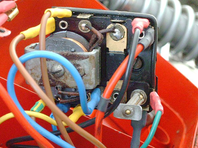
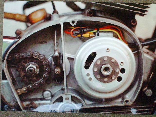 |
Unscrew the generator cover and take it off. Disconnect the wires from the old dynamo. Originally you should have there a red, a grey and a yellow/black. Disconnect equally the 2 grey wires at the ignition coil. Memorize the grey wire that went from the coil to the main switch. This is the switch-off wire and will be used again. |
|
Pull the rotor off, you will need a puller screw for this. Unscrew the old
stator and take it off the engine. Take the woodruff key from the
crank. You will not need it any more. Please do not forget to do so,
otherwise you will have trouble later on in the assembly. (Remark: This
woodruff key does not actually hold your rotor on the shaft, this is done by
the cone. It simply guides to the correct setting which will now be
otherwise achieved.)
Take the red and the yellow/black wires (running from magneto to rectifier box) and the grey wire running to the ignition coil off. |
|
|
|
|
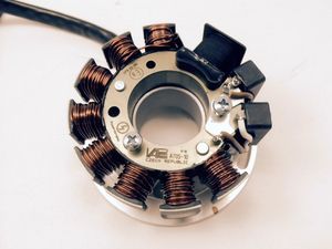 |
Have a look at the new stator unit. Opposite the small black coils you will find a small red marking on the baseplate. This is an ignition marking. |
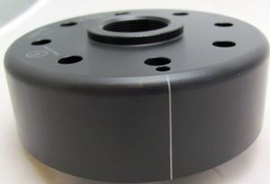 |
Have a look at the new rotor. On its circumference you will find a small pressed in marking. The marking is durable, but not well visible, especially when the rotor is fixed. So it is a good idea to highlighten the marking with some colour (simplest with a marker-pen). |
|
|
|
|
Unscrew the stator coil from the base plate
and lift it a little away from it so that you can access the mounting holes.
Take care not to damage the paint insulation of the coil.
Put the base plate with the stator hanging loosely from the unit into the place of your old generator. Put the stator coil back onto the plate, take care not the damage the wires. The stator has to snap in rather sharply. If it sets soft, you have probably squeezed a wire underneath! Make sure that the inner opening of the stator unit slots evenly over the elevated fixing rim of the base plate - otherwise the coil will sit lopsided and will tough the rotor, damaging it. Should you take the stator completely off the base, make a note though which of the 2 openings the wire went. If you change that, your timing marke will be 120 degrees out of place. |
|
|
|
|
| Take the spark plug out and bring the piston into top dead center position (TDC). As this is difficult to do with the kick lever, place the new rotor onto the crankshaft (do not screw it down) and use it as a handle to turn the crank. | |
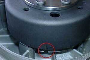 |
Once TDC has been found, carefully disengage the rotor again without moving the crank shafts position from TDC. Than place it in such a way back, that the marking on the rotor aligns with the red marking on the base, as shown in one of the pictures above. |
|
|
|
|
Fasten the new rotor by screwing it down. Make sure not to change the crank position. Put the spark plug in again. |
|
|
|
|
It might well be that after some test runs you may wish to modify timing a
little. You may change timing by:
|
|
|
|
|
 |
You need to deactivate the old rectifier box by shortcircuiting it with wires. |
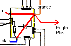 |
You will have to connect the following pins as shown here with red wires.
That is to connect into one:
|
|
|
|
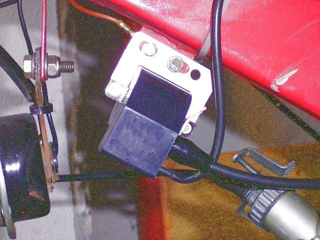 |
The new ignition coil should be fixed where the old coil had been.
You will further have to find a place for the new regulator/rectifier and the advance unit. |
|
|
|
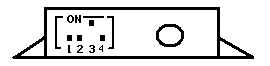
| Before installing the advance unit, have a look at the small switches at the advance unit. They activate different characteristics. There are 4 switches. | |
|
The setting needed for Gilera, 24° at start, 36° at 3,000 revs and 39° at 5,000 revs, are activated with switches 1, 2 and 4 to OFF and 3 to ON. |
|
|
|