Powerdynamo brings new ignition & light
to your vintage motorcycle
![]()
![]()
![]()
![]()
|
|
Powerdynamo brings new ignition & light |
|
|||
|
|
|||||
|---|---|---|---|---|---|
| Assembly instructions for PD systems with ignition only |
version 04.04.2012 |
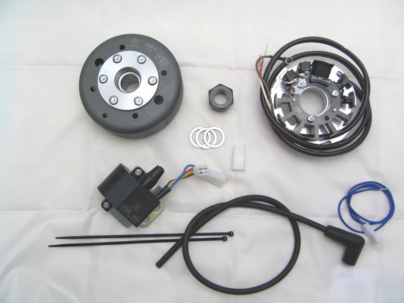 |
You should have received those parts:
|
|
|
|
| Make sure your Bultaco rests securely on her stand, preferably on an elevated work bench and that you have good access to the generator side of the engine. Note that you will install a 12 volts system, so you will need to replace all lightbulbs to 12 volt ones. | |
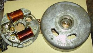 |
Disconnect the wires from the old magneto. Pull all wires out of the engine
housing.
Take the woodruff key from the crank. You will not need it any more. Please
do not forget to do so, otherwise you will have trouble later on in the
assembly. (Remark: This woodruff key does not actually hold your rotor on the
shaft, this is done by the cone. it simply guides to the correct setting which
will now be otherwise achieved.) |
|
|
|
|
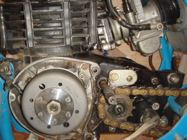
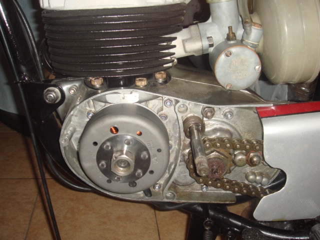
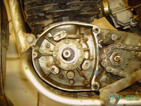
To our knowledge, there are two versions of how the alternator cable is led out of the engine! The left image shows how the cable is led to the front and the right image shows the version in which the cable goes out at engine bottom. |
|
 |
|
|
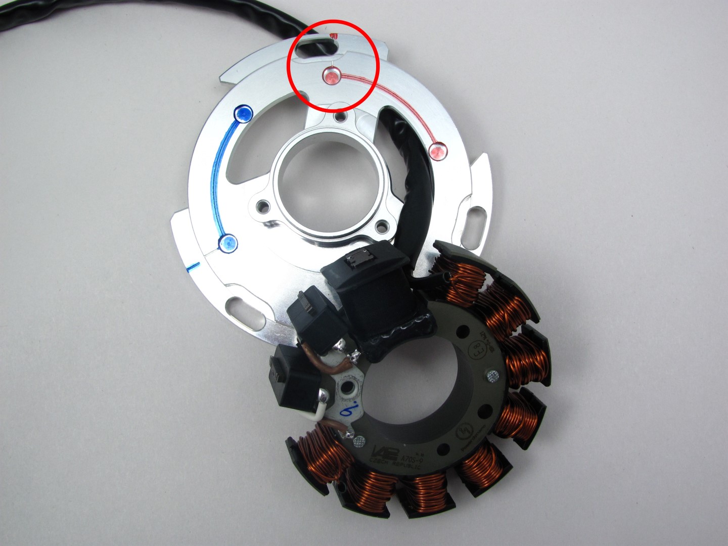
We have therefore provided two options for cable management in our material. We pre-assemble the one shown here to the left with valid red marking. |
|
 |
|
|
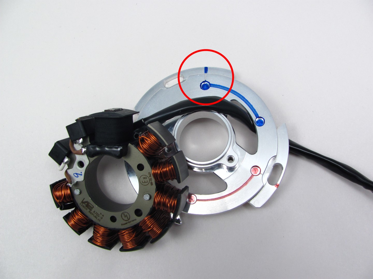
Should you want to use the other wire exit
please take the three stator fastening-screws off, pull out the stator from
the support set it again with the wire through the other opening. Make
sure to secure it again with three screws M4x25! Please make sure that the stator
comes to sit evenly and that no wires are pinched somewhere. |
|
|
|
|
 |
Place the pre-assembled stator unit onto the engine's magneto seat and screw it down there with the 3 screws M5. Lead the wire from the new generator through the wire opening of the engine upwards along the frame (or downwards). |
|
|
|
|
|
Have a look at the new stator. You will find a little left to the 2 smaller black coils the ignition marking. |
|
|
|
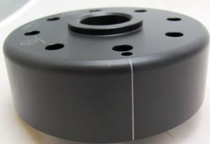 |
Have a look at the new rotor. You will find on its circumference equally some marking ( a pressed or lasered in line). Both markings have to align at the moment of ignition. Take the spark plug out.
Place the rotor loosely onto the crank and check that it may move freely
above the statorbase. |
|
Take the rotor carefully off again without changing the crank's
position and reset it onto the crank in such a way that the marking on the
rotor aligns with the marking on the stator. In that position fasten the rotor
carefully with the provided new fastening nut and the 2 washers provided.
Make sure not to alter the crank's position during that operation, otherwise you have to redo the procedure. |
|
|
|
|
|
Remark:
To get maximum flexibility no groove has been put into the rotor. No need to
worry over the now lost woodruff key. It did not have an arresting capacity, it
was guiding to correct ignition settings. Now you have the markings and a much
greater flexibility.
Now you have adjusted the ignition on standard value. Theoretical you can adjust that in any required position, you have only to turn the rotor (without changing the crank shaft position). |
|
|
|
|
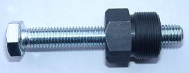 |
To disengage your new rotor again, use only a puller M27x1,25 (part 99 99 799 00).
Note: Never use a claw puller, a hammer or any other device, that will shake the magnets off. |
|
|
|
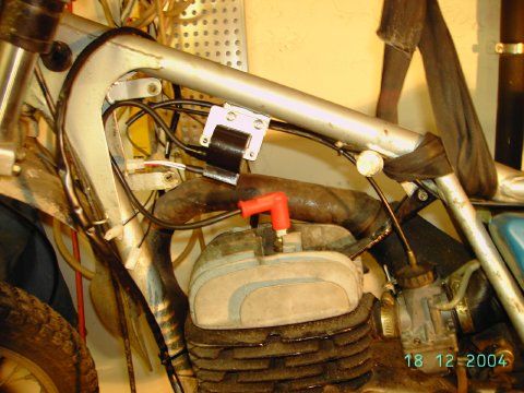 |
Fasten the ignition coil on the frame of the motorcycle, best there, where the original coil was. As position of the fastening holes might not exactly match you might need to make some adaptation. |
|
|
|
|
|