Powerdynamo brings new ignition & light
to your vintage motorcycle
![]()
![]()
![]()
![]()
|
|
Powerdynamo brings new ignition & light |
|
|||
|
|
|||||
|---|---|---|---|---|---|
| Assembly instructions for System 71 56 799 00 |
Version 19.03.2010 |
|
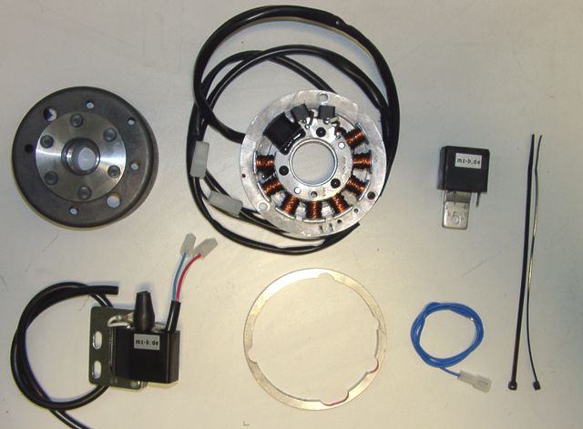
You should have received those parts:
|
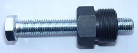 |
To disengage your new rotor again, you will need a
puller M27x1,25 (part-no.: 99 99 799 00 -Not provided!-).
Note: Never use a claw puller, a hammer or any other device, that will shake the magnets off. |
| Make sure your motorcycle rests securely, preferably on an elevated work bench and that you have good access to the dynamo side of the engine. | |
|
|
|
|
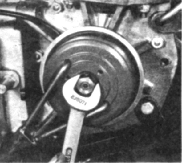
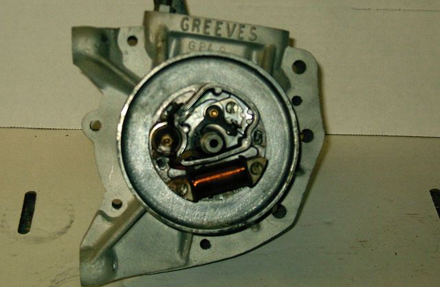
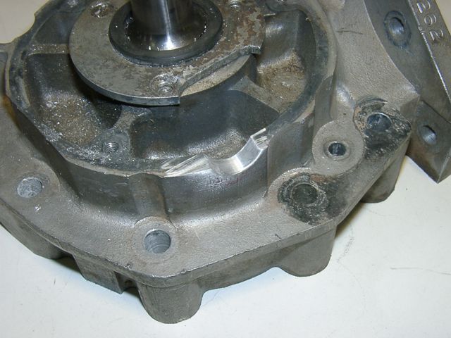
Take the Motoplat rotor off, disconnect all wires to the old magneto
and take all magneto parts out. (pictures shows Stefa)
Take the woodruff key from the crank pin. It will not be needed anymore and prevent assembly. If you forget this right at start, you will have to take the whole new unit off again to get access to the key. |
|
 |
|
|
|
|
 |
You will have to modify the magneto seat of the engine a little by bringing in a wire exit (ca. 12mm diameter). |
|
|
|
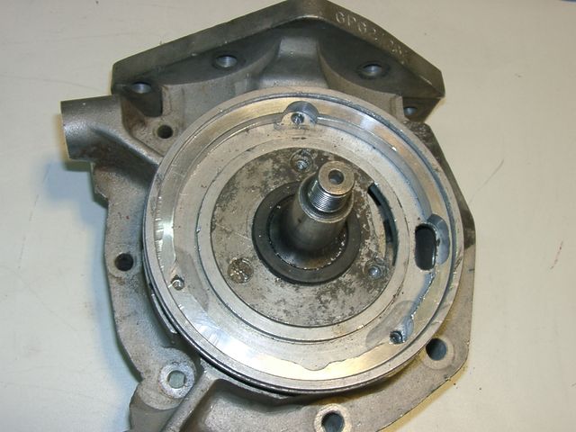 |
You will further have to check whether the new spacer ring can be evenly put
into the the magneto backplate (it is more likely than not that it is not even).
Better machine it a little to get it even. The ring has to be absolutely even at
90° to the centre of the crankshaft.
It is correct that the ring will come to rest about 2mm below the rim of the backplate. That is to take the stator unit. |
|
|
|
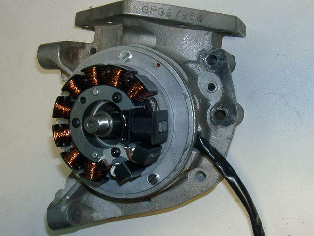 |
Now set the stator assembly in. Make sure that is sits well in its new home and
that the wire underneath is not jammed somewhere (that would result in
ignition failure).
Attention: There is no reason to remove the stator from its mounting plate. But if you do remove it, please make sure to reset it to its correct location and not to jam any wires under it. |
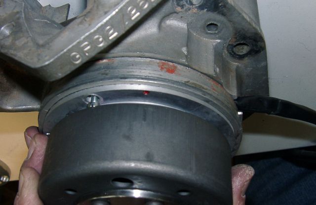
| Please note the small red marking on the statorplate. This is an ignition marking. (More of that further below!) | |
|
|
|
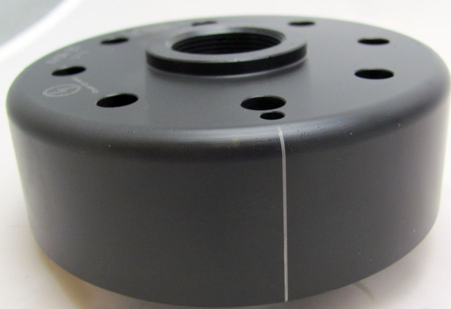 |
Have a look at the new rotor. You will find on its
circumference a small pressed in line. That is an ignition marking.
It is durable, but not well visible, so better highlighten it with
some marker pen.
(In the picture it is highlightened white.)
To get maximum flexibility no groove has been put into the rotor. No need to worry over the now lost woodruff key. It did not have an arresting capacity, it was guiding to correct ignition settings. Now you have the markings and a much greater flexibility. |
|
|
|
 |
Place the rotor loosely onto the crank and check that
it may move freely above the statorbase.
Take the spark plug out and bring the piston into wanted ignition position. Might be 2mm BTDC. |
| Take the rotor carefully off again without changing the crank's position and reset it onto the crank in such a way that the marking on the rotor aligns with the marking on the base. In that position fasten the rotor carefully with the original nut. Place under the nut the supplied spacer. | |
|
|
|
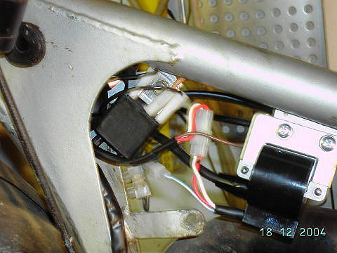 |
Fasten the new electronic regulator
and ignition coil at an convenient place. Say under the tank as
shown here (on a different motorcycle).
Before you fix the coil, screw in the high-tension cables. Lay the new generator cables along the frame (using the enclosed cable binders), in that way, that they finished close to the regulator resp. ignition coil. Take care that nothing's pinched. |
|
|
|
|
|