Powerdynamo brings new ignition & light
to your vintage motorcycle
![]()
![]()
![]()
![]()
|
Powerdynamo brings new ignition & light |
|||||
|
|
|||||
| Assembly instructions for system 70 83 999 00 |
Version 07.09.2010 |
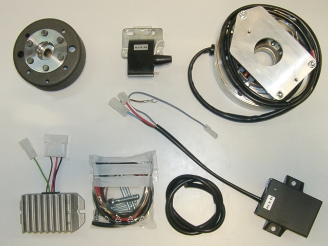 |
You should have received those parts:
|
|
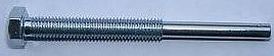
To pull the old rotor, you will need a puller tool M8x90 (part-number: 70 80 899 90 -Not provided-). |
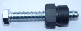 |
To pull the new rotor again, you will need a puller tool M27x1,25 (part
99 99 799 00 -Not provided-). Note: Never use a claw puller, a hammer or any other device, except a M27x1.25 puller. You risk rotor damage. |
|
|
|
| Make sure your bike rests securely on her stand, preferably on an elevated work bench and that you have good access
to the generator side of the engine. You will have to move the front fork for better
access to the generator. Disconnect your battery and take it out of the motorcycle. Note, that you will be installing a 12 volt system, so you will either need a 12 volt battery or you use the option of driving without. You will still have to replace all lightbulbs to 12 volt ones. The horn may stay at 6 volts. For driving without battery, please note our information on driving without battery. |
|
|
|
|
 |
|
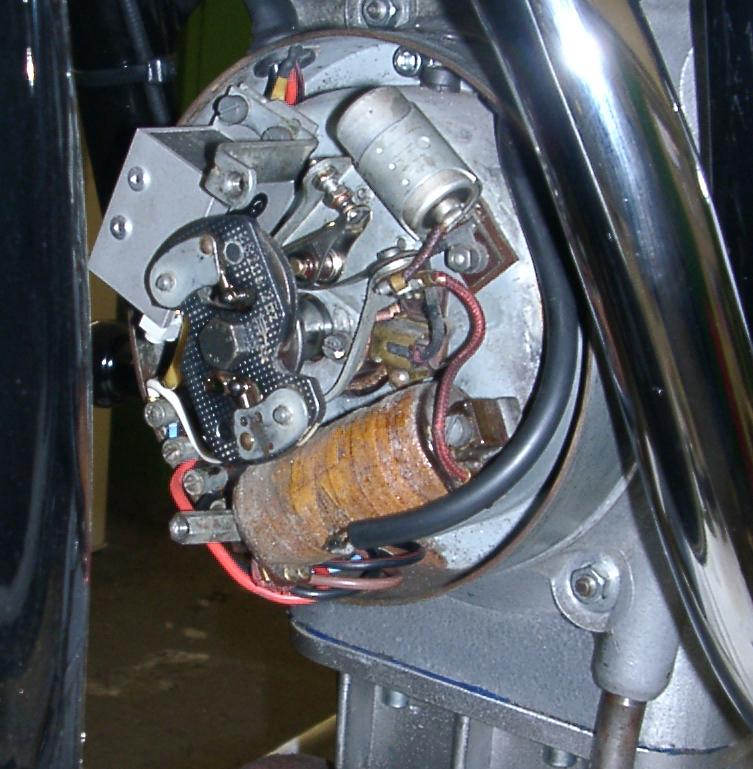
Take the generator cover off and disconnect all wires running to the dynamo. Normally that
should be:
Pull all the cables out of the motor case, but do not cut them off. |
|
|
|
|
|
After fitment of the new ignition parts rewire as follows:
Note that: Rewiring depends a little on your specific situation, that is
|
|
Integration between the original general electric system (lighting, horn etc.) and the new system is at the battery (or should you drive without at the wires normally running to the battery). |
|
|
|
|
|
Take the central screw off, that holds the stock rotor and the centrifugal governor on the crank shaft. Remove the centrifugal governor. Put the vehicle into first gear to get some resistance to the movement. Take the three mounting screws off which fix the dynamo body to the
engine and take it off. You might need a few gentle strokes with a
rubber-headed mallet to get it off. Take the woodruff key from the crank. You will not need it any more. Please do not forget to do so, otherwise you will have trouble later on the assembly. (Remark: this woodruff key does not actually hold your rotor on the shaft, this is done by the taper. It simply guides to the correct setting which will now be otherwise achieved.) |
|
|
|
|
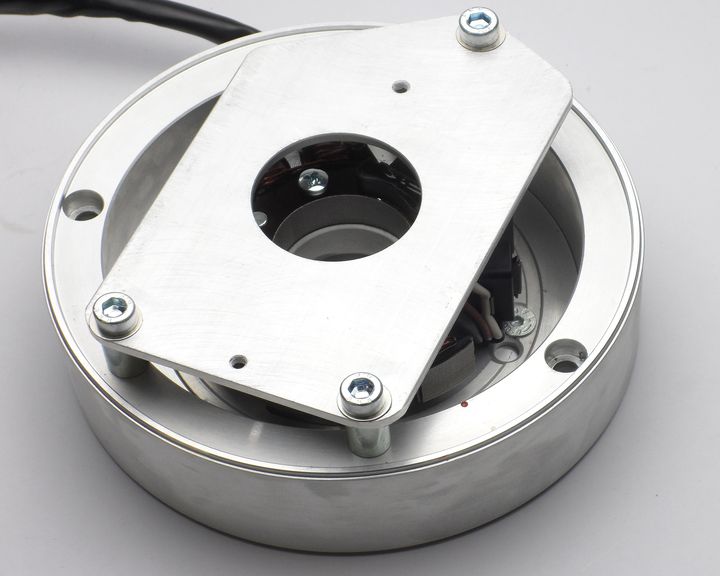 |
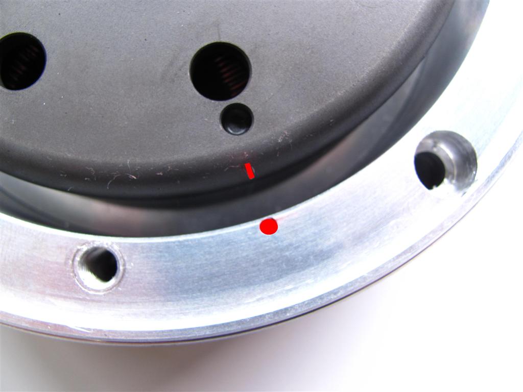
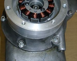
Have a look at the new stator body. You will find there on the top of the side
wall a little red
marking. As here encircled red.
This is an ignition marking. |
|
|
|
 |
Take a look at the new rotor. You will find on its circumference a red
marking as well.
Again anignition marking. With the crank in TDC position (that is the highest the piston will get) both markings should align. |
|
|
|
|
Place the pre-assembled new generator unit onto the engine and fasten it there with the 3 screws M5x50 provided. |
|
|
|
| Remove the spark plug. Place the rotor loosely onto the crank and check that it may move freely above the stator. Bring the piston in top dead centre position (TDC), the highest position of the piston. To help this, place the new rotor handtight onto the crank for turning the shaft. | |
|
Once TDC is found, take the rotor carefully off again without changing the crank's
position.
Than, reset it onto the crank in such a way that the marking on the rotor aligns with the marking on the base. If there is any change in the crank's position, you have to start again. |
|
|
|
|
Fasten the rotor carefully with the hex screw M8x35 (Please don't
forget to use the washer). Screw the
spark plug back in the cylinder. Now you have adjusted the ignition on standard value. Theoretical you can adjust that in any position, you only have to set the rotor differently relative to the crank.
If you experiment with settings, please check what you are doing by help of a stroboscope. Pleas know that wrong settings may damage the engine and produce violent kickbacks of the starter which might hurt you. Place the cover holding plate back as you have seen before assembly. |
|
|
|
|
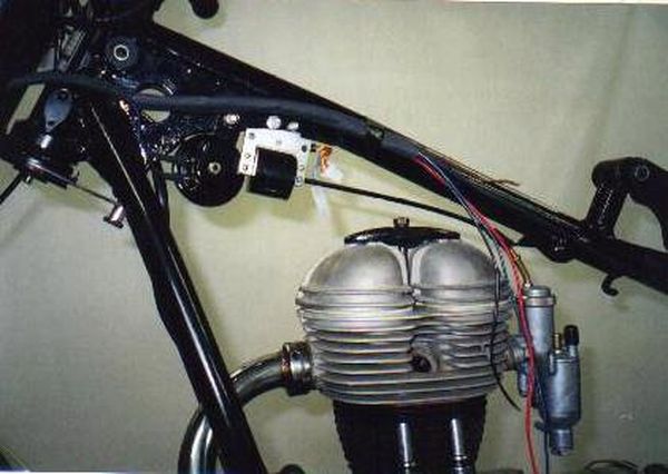 |
Fasten the new ignition coil beneath the petrol tank or on the frame.
This may vary from type to type. |
|
|
|
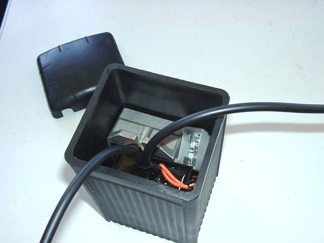 |
You will also have to fasten the new regulator/rectifier and the advance
unit (the black box) on your bike.
If you opt to drive without an battery, you can place the parts into an empty battery case. For the installation in an battery case you have to cut off a mounting lug from the advance unit. This is not considered a breach of warranty, as long as you do not cut into the box itself. |
|
|
|
| Have a look at the little blue dip-switch block on the upper narrow side of the advance unit. There are 4 little switches selecting individual ignition advance curves. | |
 |
The curve for the R25/26 is activated as shown here. That brings full ad vance of 40° at 3000 revs/min. |
 |
Should you want to have full
40° advance only at 3.500 revs onwards use this setting. In our experience full advance from 3000 onwards as indicated above is the better solution. |
|
|
|
|
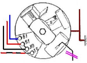
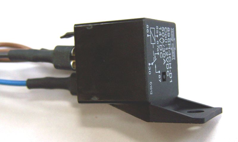
Switch-off relay ??
|
With the pack comes a relay. For its wiring see further below.
As later R25 and (normally) all R26 have a main switch that sports an (unused) pin 2, the blue kill wire from the advance may be directly connected to this pin 2 with the relay completely left out. For a wire diagram without relay see diagram 91ik12. |
|
|
|
|
|